Even with the entry that I just posted today, I am probably still at least two or three entries behind on this blog. It takes at least a couple hours to write an entry of any considerable length, and I often just don't feel like sitting down and doing it.
However, in the interest of providing more information about what's going on, and in a format that will be incredibly easy for me to update, I have just set up an Instagram account which will allow me to quickly post photos. Most of these will probably be related to the Matilda project, and will probably serve as "sneak peaks" at stuff that will be covered in future blog entries. Some of it may just be stuff that I think it looks cool. Maybe that will end up being most of it, actually, I don't know. We'll see.
The good news is, you don't actually need an Instagram account to see the photos (...I think...). You should be able to see them just by going to this URL: http://www.instagram.com/golikehellmachine
Monday, May 11, 2015

OK, then what?
Warning: this entry is
pretty dry, bordering on technical. I tried not to go into too much
fundamental explanation, figuring that anyone who doesn't already have a pretty
good handle on engine operation will probably not be interested, anyway.
OK, so,
the oil pan was eventually painted and mounted, and then ... what?
Well, I
put the engine back on the frame, and I was getting ready to bolt the
bellhousing and transmission up when I remembered that I'd never checked
pushrod length. But, to check pushrod length, I'd need to be able to turn
the engine, and my transmission came with all kinds of warnings about what not
to do before it's been spun by the engine in neutral with oil in it, to the
point where I decided I didn't even want to turn it by hand at this time, if I
didn't have to. And if it was bolted to the engine, then the engine would
be turning the input shaft as I rotated the engine. So, for the time
being, I supported the motor plate (which forms the front face of the bellhousing)
with a jackstand until I could finish checking pushrod length.
Next, all
I had to do was check pushrod length. I thought I remembered how to do
that, but decided first I'd read up and make sure that what I thought I
remembered was correct. Boy, was that ever a mistake.
Once I
started looking around online, things only became less and less clear. As
with most things online, check three message forums, get 37,462,954 different
answers. The method I thought I remembered was to check the travel of the
rocker tip across the valve stem tip, and to center that travel on the valve
stem tip. The idea is that you don't want the rocker pushing on the valve
stem tip off center, because that will cause the valve to rock in the valve
guide, which will prematurely wear out the valve guide. The thought is
that if you don't set pushrod length correctly, the valvetrain will wear out
much faster. And if you do set it correctly, you'll have an invincible
engine that runs forever and ever, and ever, and ever, and ever. And
ever. And--in some cases--ever. And I want that. So I decided
I'd better be very careful about getting my pushrod length correct.
You can
check the travel by coloring the valve stem tip with a marker, then turning the
engine by hand through two crank revolutions (one cam revolution), and then
checking where the marker ink has been wiped off the valve stem tip.
But, if
you're using hydraulic lifters, like I am, then you need to do something to
keep the lifters from collapsing while you turn the engine. If the
lifters are allowed to collapse, then th rocker will not move through its full
range of motion and you won't get an accurate representation of where the
rocker tip travel is positioned on the valve stem tip. So, one method is
to use solid lifters just for checking pushrod length, and then install the
hydraulic lifters. Another method is to use "checking springs"
in place of your valve springs. Checking springs are very lightweight
springs which you can compress by hand, and which will not collapse the
hydraulic lifters ... as much as the valve springs would.
Here's a
photo showing the standard valve springs (cylinder 8, the two springs on the
left) and the checking springs (cylinder 6, the two springs on the right):

Before
this project, I had two different styles of valve spring compressor. One
style can only be used with the cylinder head off of the engine. It's
shaped like a big "C," and it reaches around the cylinder head to
push up on the head of the valve while it pushes down on the valve spring
retainer on the other side of the head. That wasn't an option here, as
the heads are already on the engine. I had another style which is made to
grab the sides of the valve spring and pull up while it simultaneously pushes
down on the valve spring retainer. I thought that would work, but then
realized that since these heads have double valve springs on each valve, an
inner and an outer, it wasn't going to work because it couldn't grab the inner
spring. So, I ended up ordering a third style
of valve spring compressor. This one threads down on to the rocker stud
and has a fork that presses down on the valve spring retainer. I pulled
the spark plug from whichever cylinder I was working on and stuffed a length of
windshield washer hose into the cylinder to keep the valve from dropping into
the cylinder. The really nice thing about this tool is that the lever for
compressing the valve spring will lock into position at full travel, so you can
have both hands free for fishing the keepers out.
Anyway,
here's a view of the tops of the cylinder 6 valve stem tips, with black stripes
drawn on them with a Sharpie:

And
here's the results of turning the engine through one complete cycle (two crank
revolutions, one cam revolution), with the standard length pushrods:

These
look pretty good, but the mark on the exhaust valve (left) looks like it's
shifted a little bit down, toward the outboard side of the engine, and the mark
on the intake valve (right) looks like it's shifted a little bit up, toward the
inboard side of the engine. This would indicate that the pushrod on the
exhaust valve is a little long, and the pushrod on the intake valve is a little
short.
The
critical piece of equipment for checking pushrod length is a couple adjustable
pushrods. You can't run the engine with these, but you can use them to
try different pushrod lengths while checking. There are different styles,
but the ones I got have one piece threaded into the other, and they are a
certain specified length when screwed all the way in. Then each turn that
you unscrew them adds 0.050" to that length. So you change the
length and check the result, change the length and check the result, and repeat
until it looks good, and then you count the turns back to minimum length, do a
little math, and that's the length you need.
Here's a
picture of the marks with both pushrods at a pretty good length:

But wait
... we're not even CLOSE to finished.
Next a
million things happened to complicate everything.
First
off, in spite of the fact that Comp Cams states in a (pretty disappointing)
video on YouTube that their checking springs are weak enough that they won't
compress hydraulic lifters, it turns out that that is not true. I
eventually discovered that I was not reaching full valve lift because the
lifters were still collapsing, even with the checking springs installed.
That means that all the stuff I did above was inaccurate.
But, like
I said, there are several theories on what's the correct way to determine
"optimal" valvetrain geometry. The reason I discovered that I
wasn't reaching full lift was because I wanted to try one of the alternate
methods, which was to set pushrod length so that the rocker arm is at a
90-degree angle to the valve stem at half lift (or, an alternate theory says two-thirds
lift, to shift the optimal geometry towards full lift, where spring forces are
at maximum). I will also mention now that another theory says that you
want to minimize the width of the rocker's travel across the valve stem tip,
regardless of where this puts the rocker on the valve stem tip. If you
think about it (and I did think about it ... waaaay more than it was probably
worth), this "minimum width" theory should give the same result as
the 90-degree-at-half-lift theory. They are just two different ways of
measuring the same result.
Anyway,
to check where your rocker is at half lift, you have to know when you're at
half lift. To check when I was at half lift, I used a dial indicator.
The dial indicator showed, however, that I wasn't getting anywhere near
full lift, which was how I realized that the checking springs were still strong
enough to collapse the lifters.
Here is a
photo of the engine set up with the dial indicator riding on the valve spring
retainer for the cylinder 1 exhaust valve:

And here,
for the record, is where the rocker travel ends up if I tried to minimize its
width, and/or put the rocker at a 90-degree angle to the valve stem at half
lift:

You can
see that the mark is way off center, shifted to the outboard side of the
engine, indicating a short pushrod (according to the other theory). In
fact, the pushrod was so short that the rocker was rubbing on the lash
adjusting nut when the lifter was on the base circle. That's the kind of
thing that tells you ... "something's not right here." Now,
it's possible that by choosing a different rocker, or changing some other
variable, I might have been able to shift that mark toward the center of the valve
stem tip while still retaining a minimal width of travel and holding my
90-degrees-at-half-lift target. But all these parts are supposed to be
correct for this engine, and I didn't feel that it was likely that I should
have to do all that. I decided that it was more likely that these methods
were incorrect, and that they were being championed by people who were either
misinformed, misguided, or possibly familiar with this method from working on
some other type of engine.
As I was
questioning these other methods, I went back and very carefully reviewed Comp
Cams' instructions for optimizing pushrod length. Their instructions
described the rocker arm moving from the inboard side of the valve stem tip
towards the outboard side of the valve stem tip at full lift, and then back
towards the inboard side. If the rocker were at a 90-degree angle to the
valve stem tip, with a minimized width of travel across the valve stem tip,
then it would have to reach its outboard-most point of travel at half lift,
moving back to its inboard-most point at full lift, then back to its
outboard-most point, and back to its inboard-most point when the lifter was
back on the base circle. This is not what they described, so I threw out
the 90-degree/minimum-travel theories and returned to the centered-travel
theory.
As an
aside, one of the people I'm working with from the client on my current project
at work used to be involved in Ford's NASCAR program. I asked him one day
if he knew how the Ford NASCAR guys defined optimum valvetrain geometry.
He said that rocker tip travel was supposed to be centered on the valve
stem tip, which confirmed the theories that I was favoring by this point.
I asked him, "That's how the Ford guys do it?" He said,
"I think so, yeah." I faked a look of concern, and then I asked
him, "Well, did you ever happen to find out how the Chevy guys do it?
You know, if I wanted to do it the right way?" He rolled his
eyes and threw up his hands and said, "Well, I could call somebody, if you
really want to know...!!" I said, "No, no, no, I wouldn't want
you to interrupt them, they're doing important work."
Anyway,
now I'd finally decided what method I was going to use, it was just a question
of crunching through it. Working through the cylinders, I put checking
springs on each one, put a dial indicator on each valve, and turned the engine
to where it stopped lifting the valve. That should be the full lift
position for the camshaft, and then I could just push the valve spring retainer
down by hand until the valve reached full lift. You can actually feel the
spot where the lifter plunger spring is no longer helping you to open the
valve, representing full lift. By this method I could check the position
of the rocker tip on the valve stem at full lift.
I found
some small variations from cylinder to cylinder, but averaged them all out and
ended up with measurements for intake and exhaust pushrods slightly shorter
than the ones recommended by Comp. This makes sense, as I believe the
engine block has been decked, which would shift the cylinder head down and
require slightly shorter pushrods. So I sent the measurements to Comp and
they sent me the corresponding pushrods, which are now in the engine.
All in
all, I still can't really be sure if I "got it right." Did I
use the right method? Like so many debates on the internet, nobody has
hard facts to substantiate their argument for why their method is
"right." Did I get the measurements right? I did my best,
but can't be sure. But I took all the information available, tried some
things, tried to decide what made sense, made a decision on how to proceed, and
then considered the result, to try to decide if it made sense. I think it
does.
All this
deliberation probably added at least a month, maybe two, to the project.
Was it worth it? Well ... probably not, really. The more I
considered all these ideas, the more I slowly came to feel that it probably
doesn't really particularly matter. I suspect that the importance placed
on valvetrain geometry is probably a carryover from the days of stamped steel
rockers. The tip of a stamped steel rocker had to be carefully contoured
so that its contact point with the valve stem tip would always be oriented to
press straight down on the valve stem tip, regardless what angle the rocker was
at as it traveled through its full range of motion. That contour on the
rocker tip can only be wide enough to be effective for a certain window of
rocker arm travel, i.e. a certain window of pushrod lengths. Outside of
that window, the rocker arm tip would be a flat surface pushing on the valve
stem tip's flat surface at an angle, which could push sideways on the valve
stem tip and apply a torque to the valve, wearing the valve guides. Nowadays,
though, roller rockers are so popular, they virtually render stamped steel
rockers irrelevant. Roller rockers have a small roller built into their
tip, which ensures that the force transmitted from the rocker tip to the valve
stem can only be directly in line with the valve stem. I suspect this
design feature makes valvetrain geometry much less critical. Just like
everyone else arguing these points on the internet, however, I have no hard
evidence to support my claims, which is why I still went through a month or two
of trying to determine the optimal pushrod length for my engine.
Anyway,
at this point pushrods are done, I feel pretty good about what's in there, and
I'm moving on.
Thursday, March 12, 2015
stuck in painting Hell
I love to order car parts. The project is frequently derailed by various problems, which can be something as small as realizing that I still haven't ordered some part and now I need it, or something more complex, like realizing that there are a lot more complications to installing a roller cam in an old non-roller engine than I ever originally thought, or trying to figure out how to get my headers up off of my steering box. In any case, trying to find the right part to solve a problem or fit an application can be like a puzzle combined with a scavenger hunt. And it's really amazing how long those puzzles and hunts can take in a lot of cases, even for the ones that seem simple. I love Summit's website, though, because they make it so searchable. You can sort and filter the results of a search in so many ways, it can lead you to things that you didn't even know existed, but which might be just what you need (or at least want).
The best part of the process, though, is the feeling of having just ordered a part. At that point, the puzzle has been solved, the project is back on track, if somewhat delayed, and all you have to do is sit back and wait for the part to arrive. Then the part shows up and it's like Christmas. Then the part doesn't fit, and ... well, let's not think about that right now.
When I ordered an oil pan, I sorted by my engine type, my car type, and by orange paint, because I wanted it orange, and I didn't want to have to paint it. I also picked this specific pan because it has a custom-fabricated enlarged sump with an internal baffle to control sloshing and keep the oil pickup submerged. That's all "race car stuff" that I don't really need at all, but which I think is neat, and is not prohibitively expensive, so I'm going to have it.
Unfortunately, as I mentioned in the last post, I had to pull the engine back off the chassis due to an interference between the oil pan and the steering linkage. The larger sump (which I don't really need) interferes with the center drag link in the steering linkage. According to the information listed on Summit, the pan was supposed to fit my application, but when I put it all together, there was just a very slight interference when the wheels were turned all the way to one side.
Part of the problem was probably that I had installed aftermarket control arms, and a disc brake conversion kit which required modifying the steering arms, and all of this may have contributed to changing the geometry of the steering linkage. It may have been further complicated by the fact that the steering box on the '65 Impala is mounted behind the front wheels, which puts the steering linkage between the oil sump and the chassis crossmember. Bertha, my 1972 Monte Carlo, had the steering box mounted in front of the front wheels, which puts the steering linkage in front of the crossmember and nowhere near the oil sump. Same goes for a Chevelle, which is probably a much more popular application than a 1965 Impala, so less likely to generate complaints to the manufacturer of the pan.
In fact, 1965 Impala projects seem to tend to be of the type that get either a stock oil pan, or maybe a chromed stock oil pan. It's possible I might be the first person to ever put this particular style of oil pan on a big block in a 1965 Impala. Who knows. In any case, the oil pan and the center drag link want to be in the same spot, and that's no good.
So, I pulled everything off the chassis and put the engine back on the stand. As received, without modification, the front of the sump was pretty much just a vertical wall. I didn't really get any pictures of it before modification, but you can kind of see it in this picture from the Summit website:

The interference was so slight, I originally thought maybe I could just bend the front of the sump to form a "pocket" that the centerlink could tuck into when the wheels were turned. I didn't want to cut up the pan and then have to get it welded back together if I could avoid it, so I decided to try smashing it with a hammer, instead.
Before I pulled everything off of the chassis, I marked the vertical centerline of the centerlink on the front of the oil pan. After I had everything apart, I took a section of an old jack handle and used a couple ratchet straps to clamp it on to the front of the sump. I put some masking tape on, too, in a foolish hope that maybe it would keep me from messing up the paint job too bad.

Once I had that all set up, I pretty much just started whaling away on the jack handle with a hammer. The next couple pictures show how the front of the sump started to cave in to form the desired pocket. I tightened the ratchet straps as necessary to hold everything together.


Of course the paint was pretty messed up, so I did have to re-paint the pan at that point. Good thing I ordered an orange one, so I wouldn't have to do that.
After mashing and painting:

Re-installed on the engine

So then everything went back on the chassis. The centerlink tucked up into the pocket nicely. There was probably still less clearance than I should have had, but I decided it was good enough, and I pressed forward.
At some point, I decided it was probably time to think about mounting the exhaust headers. After wrestling one header up into position, I found that it was going to be impossible to install the headers, because the mounting flange interfered with the nuts on the cylinder head studs. The stock cylinder head bolts sit relatively flush to the cylinder head, whereas the aftermarket studs that I decided to use stand up a little bit taller. Why do I need studs? I don't, I just decided it would be cool to have them. When you start talking about bolts vs. studs, everyone mentions that if you use studs, you'll have to remove your brake booster if you want to remove the heads with the engine in the car. Nobody mentions that your header flange will hit them. But in my case, it did.
I figured I must not be the first person to have this problem, so I started doing some research online. A lot of people talked about installing bolts for the row of fasteners below the header flange, and using studs for all the other cylinder head fasteners. I didn't really want to backtrack and re-torque the cylinder heads, and I didn't want a mix of studs and bolts, so I kept looking around until I found some big block Chevy guys who said they'd just clearanced the flange with a grinder. That was what I really wanted to do, I was just doing research to see if there was anyone who said, "Here's why you should never do that...." I didn't find anyone who said that, so I decided to do some grinding.
(I am a little bit worried about how thin this makes the flange at the notch, and I wonder if they're going to crack/break there, but I couldn't find anyone else who mentioned problems like that, so ... I guess we'll just find out.)
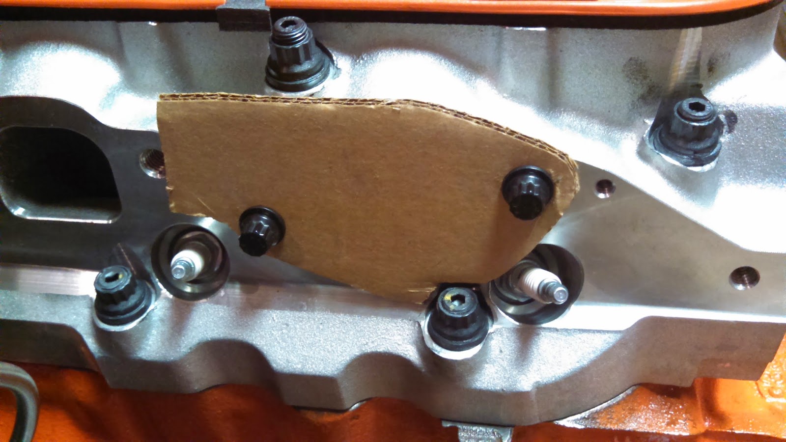
The basic shape of the header flange repeats at each exhaust port, so I just traced one part of it on to a piece of cardboard, then I cut that out, put bolt holes in it, and then cut it a little bit at a time until it cleared the stud and nut:
I used that as a template to transfer the shape of the notch on to the header flange, then I cut the notches with an angle grinder. These two pics show a "before" and "after" comparison (the flange is upside down in these pics, so the notch is at top right in the second pic):


Test fit:

After cutting the flanges, I had to re-paint the headers. I ran a piece of string from the track for the garage door opener, down through the header bolt holes, up to the garage door track, and down to a cabinet handle that I tied it off to. That allowed me to balance the headers on their outlet flanges, so I could paint all the way around them in one shot.

Once that was done, it was right back to the action. Certainly, there was nothing that could stand in the way of a smooth and successful completion of the project now.
I went to install the headers on the engine, and immediately found that the driver side header was interfering with the steering box. Now, these headers are supposed to be specifically for this engine, in this car ... maybe some false information has been distributed to the aftermarket regarding the exact location of the 1965 Impala's steering box...?
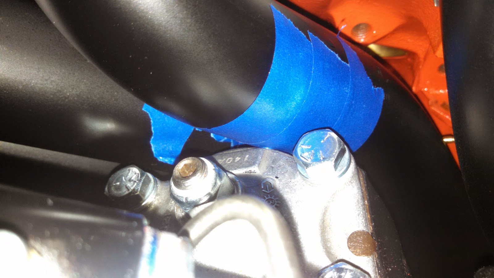

It's hard to get a picture that really shows exactly where the interference is, but it seemed to be pretty slight. The cover on top of the steering box there is aluminum, and looks to be really beefy, so I thought maybe I could just file off some of the beef to create some clearance.
If you watch TV shows about car projects, or read magazine articles about car projects, or pay attention to car projects at all, you've probably heard a story about a problem with header clearance. It seems to be a commonly accepted "fix" to just put a dent in the header primary to create clearance, but I've always hated that solution. It seems like you're just "solving" one problem by creating another. Still, a lot of "pros" seem to think it's OK. But I didn't want to do that, and I figured that if I did do it, then I'd have to give up my right to complain about other people doing it. I don't know if taking a file to the steering box cover is really any better than putting a dent in the header primary, but ... in my mind it was, I guess.
I had the engine on the hoist and not resting on the engine mounts as I was doing all this. I'd hoist it up a bit, file some, and then lower the engine to check clearance. Every time I lowered the engine, though, it just dropped right through all the clearance I'd created until it was resting on the steering box again. Apparently I was off by more than I thought.
A portrait of the artist as a guy trying to figure out why his headers are all over his steering box:

OK, so now a story about engine mounts.
I decided to start by calling Hooker Headers, to see if they had any comments about what my problem might be. They asked if I was using big block mounts or small block mounts. I told them I don't know. There is a lot of interchangeability of parts, by design, in the engine mounts, and I don't really know what I have. I know there are a couple different styles of mounts, but I've never been able to get a definitive answer on what the different styles are supposed to be for. Part of the reason I got what I got was because the frame already had frame mounts on it, so I just looked around until I could find a set of engine mounts that would mate to the frame mounts. I suspect the car originally came with a small block, so those frame mounts may have been intended for use with a small block, but I don't really have any way of knowing any of that for sure, either. The VIN only identifies it as an SS V8 car, it doesn't code the specific size of V8. Anyway, I started looking around online to try to find out, what is the big block style, what is the small block style, and for the different types of mount that I'm aware of, are there any dimensional differences that would affect the position of the engine once it's mounted?
The answers to those questions ended up being, "I don't know," "I don't know," and "not that I can tell." But while I was searching around Summit looking for all this stuff, I stumbled on to something I'd never heard of before: engine mount shims. There were three or four different companies selling 3/16"-thick shims that could be bolted in between the engine mount and the engine block. At the angle that the mount is bolted up, this 3/16" shim effectively raises the engine up about 1/4" vertically. I thought that sounded better than dented headers, so I ordered a set of those, AND ... longer bolts, of course, so that the bolts would reach through the shims to bolt up the mounts.
After wrestling around with the headers and trying to create clearance, I'd knocked some paint off of the headers. The shims were unpainted as received, so it was time for more painting.

Notice that this time I hung the shims on the string in between the headers, so I could paint all sides of all things at the same time.
Of course, those of you paying close attention will be saying to yourselves, "But wait a minute, if you had knocked that pocket into the oil pan to accommodate the centerlink, and now you're shifting the pocket up a quarter of an inch, doesn't that mean that your pocket is in the wrong place now?"
Yes. Yes it does. It means exactly that. So, once again, the engine came back off the chassis, and the oil pan came back off the engine. And it was clear now that it was going to have to be cut.
To be honest, I wasn't really sure exactly how this was going to work as I started cutting, but I started by going across the front of the bottom edge. I did all the cutting using a cutoff wheel on a Dremel.

Then I cut up the seams where the flat front angles back.

I started to try to bend the bottom flap up a bit, but it didn't really want to bend where I wanted it to bend, so I went back and kind of "scored" the line where I wanted it to bend. I was still using the Dremel cutoff wheel for this, but I just didn't cut all the way through.

It seemed more ready to bend now, but I cut a couple little pie slices at the corners to provide clearance for it to swing through that area.

That allowed me to fold that lower flap under everything else.

A different angle to show the same stage:

Then I went across and trimmed off the upper flap, trying to keep it tight with the other flap.

Skipped through a few steps without photos, but basically folded the ears over at the ends and trimmed them off flush with the other flaps, then ground off all the paint to get it ready for welding.

A technician at work welded it up for me, including running a bead down the scored line at the lower edge.

Good thing I ordered it orange, so I wouldn't have to paint it.
Next, I filled it with some old, used oil, and put it on the floor on top of some clean paper towels. This was my leak check. I let it sit there for a few days, and didn't find any leakage. So, I drained out the used oil, and then very carefully and thoroughly cleaned out the pan with Brakleen, trying to make sure to clean out all the debris that went into the pan when I cut it. And then it was time to paint it.
So, I painted it, but somehow this time I didn't manage to get the top side of the "wings" painted. And you could see that pretty clearly, and it looked bad, so I decided I'd paint it again. I've had bad luck in the past with spray paint flaking off, so I've been trying to follow all the directions on the can, and the can says that once the paint is dry you're supposed to allow a week of cure time before putting on more coats, so that was a week lost. Good thing I ordered it orange, so I wouldn't have to paint it.
But wait ... it gets better. The next time I painted it, the paint was dry and I picked it up to look it over, and it somehow slipped out of my hand and fell on the floor, which knocked the fresh paint off a couple corners. Maybe I subconsciously don't even want this pan painted? So I painted it one more time. After waiting another week.
But wait ... it still gets better. The can also says that it is "EXTREMELY IMPORTANT" to bake parts painted with high temp engine paint at 200degF for one hour, to finish the curing process and get full resistance to chemicals and all that. How do you bake an oil pan? Well, you put it in your oven.


Is it smart? Ohh ... probably not. But it actually worked pretty well. The box on the floor under the oven door is a digital multimeter connected to a thermocouple which is reading the temperature in the box, to make sure it's getting hot enough in there, but not too hot. There was a lot of nervous monitoring of the process. The paint is supposed to be cured at 200degF, but the insulation warns that it will ignite at 240degF, so you have to be very careful, but it is workable. I know because I did it four times. Good thing I ordered that oil pan in orange so I wouldn't have to paint it.
So, the part where it gets better is that after I painted the pan for what I thought was the last time, I baked it again, but for some reason this time the paint bubbled up all over the bottom of the pan. I'm still not sure why that happened, but it looked like junk. I tried to sand it down, but that just knocked all the bubbles off and left big "holes" in the paint all over. It looked terrible.
At that point, the pan had been painted by the manufacturer, then painted after I deformed it, then painted after I didn't get complete coverage, then painted after it was cut and welded, then painted again after I dropped it. It had at least five coats of paint on it. I was so sick of messing with the stupid thing, I thought about just giving up and putting the stock pan back on. But I also had so much time in the stupid thing at that point, I wasn't ready to just cut bait and walk away. I decided to just remove all the paint and start over.
To remove the paint, I used something like a 40-grit paint and rust removal wheel on my angle grinder. Although, I've gotta say, I really think the manufacturer of that wheel is selling his product short. It says it will remove paint and rust, but I accidentally tagged my knuckle with it once, and it turns out that it removes skin and flesh pretty effectively, as well.
Anyway, I got the pan cleaned up pretty well, then sprayed it with a high temp primer, then sprayed it one more time with Chevy orange. Baked it. All done.
But wait ... as I pulled it out of the oven, I noticed one corner that had apparently been scraped on something, which knocked the paint off of it. After a lot of cursing, I decided that I would try one more time, and whatever came out of the oven next would just have to be good enough.
So, I painted it one more time, handled it VERY CAREFULLY ... waited a week, then baked it to finish the curing process, and ... it finally came out good. Below is a side view to show how the front of the sump, which used to be a vertical wall, now slopes back at an angle for additional clearance.

Back on the engine:


Starter motor is mounted there, too.
So, as you can see in the photo two photos up, I decided to put the headers on the engine while it was on the stand this time. I wrapped old t-shirts around anything that the headers might bump into as the engine was being lowered on to the chassis, and I dropped the whole deal down into place. Plenty of clearance in front of the oil pan now, looks like almost a full inch. And between the header primary and the steering box, maybe a quarter inch. I'll take it.
This isn't all that's been going on, there's also been tremendous amounts of cursing that I didn't mention here. And I've also been doing other work on the car. And that will be detailed here, too ... eventually.
The best part of the process, though, is the feeling of having just ordered a part. At that point, the puzzle has been solved, the project is back on track, if somewhat delayed, and all you have to do is sit back and wait for the part to arrive. Then the part shows up and it's like Christmas. Then the part doesn't fit, and ... well, let's not think about that right now.
When I ordered an oil pan, I sorted by my engine type, my car type, and by orange paint, because I wanted it orange, and I didn't want to have to paint it. I also picked this specific pan because it has a custom-fabricated enlarged sump with an internal baffle to control sloshing and keep the oil pickup submerged. That's all "race car stuff" that I don't really need at all, but which I think is neat, and is not prohibitively expensive, so I'm going to have it.
Unfortunately, as I mentioned in the last post, I had to pull the engine back off the chassis due to an interference between the oil pan and the steering linkage. The larger sump (which I don't really need) interferes with the center drag link in the steering linkage. According to the information listed on Summit, the pan was supposed to fit my application, but when I put it all together, there was just a very slight interference when the wheels were turned all the way to one side.
Part of the problem was probably that I had installed aftermarket control arms, and a disc brake conversion kit which required modifying the steering arms, and all of this may have contributed to changing the geometry of the steering linkage. It may have been further complicated by the fact that the steering box on the '65 Impala is mounted behind the front wheels, which puts the steering linkage between the oil sump and the chassis crossmember. Bertha, my 1972 Monte Carlo, had the steering box mounted in front of the front wheels, which puts the steering linkage in front of the crossmember and nowhere near the oil sump. Same goes for a Chevelle, which is probably a much more popular application than a 1965 Impala, so less likely to generate complaints to the manufacturer of the pan.
In fact, 1965 Impala projects seem to tend to be of the type that get either a stock oil pan, or maybe a chromed stock oil pan. It's possible I might be the first person to ever put this particular style of oil pan on a big block in a 1965 Impala. Who knows. In any case, the oil pan and the center drag link want to be in the same spot, and that's no good.
So, I pulled everything off the chassis and put the engine back on the stand. As received, without modification, the front of the sump was pretty much just a vertical wall. I didn't really get any pictures of it before modification, but you can kind of see it in this picture from the Summit website:
The interference was so slight, I originally thought maybe I could just bend the front of the sump to form a "pocket" that the centerlink could tuck into when the wheels were turned. I didn't want to cut up the pan and then have to get it welded back together if I could avoid it, so I decided to try smashing it with a hammer, instead.
Before I pulled everything off of the chassis, I marked the vertical centerline of the centerlink on the front of the oil pan. After I had everything apart, I took a section of an old jack handle and used a couple ratchet straps to clamp it on to the front of the sump. I put some masking tape on, too, in a foolish hope that maybe it would keep me from messing up the paint job too bad.
Once I had that all set up, I pretty much just started whaling away on the jack handle with a hammer. The next couple pictures show how the front of the sump started to cave in to form the desired pocket. I tightened the ratchet straps as necessary to hold everything together.
Of course the paint was pretty messed up, so I did have to re-paint the pan at that point. Good thing I ordered an orange one, so I wouldn't have to do that.
After mashing and painting:
Re-installed on the engine
So then everything went back on the chassis. The centerlink tucked up into the pocket nicely. There was probably still less clearance than I should have had, but I decided it was good enough, and I pressed forward.
At some point, I decided it was probably time to think about mounting the exhaust headers. After wrestling one header up into position, I found that it was going to be impossible to install the headers, because the mounting flange interfered with the nuts on the cylinder head studs. The stock cylinder head bolts sit relatively flush to the cylinder head, whereas the aftermarket studs that I decided to use stand up a little bit taller. Why do I need studs? I don't, I just decided it would be cool to have them. When you start talking about bolts vs. studs, everyone mentions that if you use studs, you'll have to remove your brake booster if you want to remove the heads with the engine in the car. Nobody mentions that your header flange will hit them. But in my case, it did.
I figured I must not be the first person to have this problem, so I started doing some research online. A lot of people talked about installing bolts for the row of fasteners below the header flange, and using studs for all the other cylinder head fasteners. I didn't really want to backtrack and re-torque the cylinder heads, and I didn't want a mix of studs and bolts, so I kept looking around until I found some big block Chevy guys who said they'd just clearanced the flange with a grinder. That was what I really wanted to do, I was just doing research to see if there was anyone who said, "Here's why you should never do that...." I didn't find anyone who said that, so I decided to do some grinding.
(I am a little bit worried about how thin this makes the flange at the notch, and I wonder if they're going to crack/break there, but I couldn't find anyone else who mentioned problems like that, so ... I guess we'll just find out.)
The basic shape of the header flange repeats at each exhaust port, so I just traced one part of it on to a piece of cardboard, then I cut that out, put bolt holes in it, and then cut it a little bit at a time until it cleared the stud and nut:
I used that as a template to transfer the shape of the notch on to the header flange, then I cut the notches with an angle grinder. These two pics show a "before" and "after" comparison (the flange is upside down in these pics, so the notch is at top right in the second pic):
Test fit:
After cutting the flanges, I had to re-paint the headers. I ran a piece of string from the track for the garage door opener, down through the header bolt holes, up to the garage door track, and down to a cabinet handle that I tied it off to. That allowed me to balance the headers on their outlet flanges, so I could paint all the way around them in one shot.
Once that was done, it was right back to the action. Certainly, there was nothing that could stand in the way of a smooth and successful completion of the project now.
I went to install the headers on the engine, and immediately found that the driver side header was interfering with the steering box. Now, these headers are supposed to be specifically for this engine, in this car ... maybe some false information has been distributed to the aftermarket regarding the exact location of the 1965 Impala's steering box...?
It's hard to get a picture that really shows exactly where the interference is, but it seemed to be pretty slight. The cover on top of the steering box there is aluminum, and looks to be really beefy, so I thought maybe I could just file off some of the beef to create some clearance.
If you watch TV shows about car projects, or read magazine articles about car projects, or pay attention to car projects at all, you've probably heard a story about a problem with header clearance. It seems to be a commonly accepted "fix" to just put a dent in the header primary to create clearance, but I've always hated that solution. It seems like you're just "solving" one problem by creating another. Still, a lot of "pros" seem to think it's OK. But I didn't want to do that, and I figured that if I did do it, then I'd have to give up my right to complain about other people doing it. I don't know if taking a file to the steering box cover is really any better than putting a dent in the header primary, but ... in my mind it was, I guess.
I had the engine on the hoist and not resting on the engine mounts as I was doing all this. I'd hoist it up a bit, file some, and then lower the engine to check clearance. Every time I lowered the engine, though, it just dropped right through all the clearance I'd created until it was resting on the steering box again. Apparently I was off by more than I thought.
A portrait of the artist as a guy trying to figure out why his headers are all over his steering box:
OK, so now a story about engine mounts.
I decided to start by calling Hooker Headers, to see if they had any comments about what my problem might be. They asked if I was using big block mounts or small block mounts. I told them I don't know. There is a lot of interchangeability of parts, by design, in the engine mounts, and I don't really know what I have. I know there are a couple different styles of mounts, but I've never been able to get a definitive answer on what the different styles are supposed to be for. Part of the reason I got what I got was because the frame already had frame mounts on it, so I just looked around until I could find a set of engine mounts that would mate to the frame mounts. I suspect the car originally came with a small block, so those frame mounts may have been intended for use with a small block, but I don't really have any way of knowing any of that for sure, either. The VIN only identifies it as an SS V8 car, it doesn't code the specific size of V8. Anyway, I started looking around online to try to find out, what is the big block style, what is the small block style, and for the different types of mount that I'm aware of, are there any dimensional differences that would affect the position of the engine once it's mounted?
The answers to those questions ended up being, "I don't know," "I don't know," and "not that I can tell." But while I was searching around Summit looking for all this stuff, I stumbled on to something I'd never heard of before: engine mount shims. There were three or four different companies selling 3/16"-thick shims that could be bolted in between the engine mount and the engine block. At the angle that the mount is bolted up, this 3/16" shim effectively raises the engine up about 1/4" vertically. I thought that sounded better than dented headers, so I ordered a set of those, AND ... longer bolts, of course, so that the bolts would reach through the shims to bolt up the mounts.
After wrestling around with the headers and trying to create clearance, I'd knocked some paint off of the headers. The shims were unpainted as received, so it was time for more painting.
Notice that this time I hung the shims on the string in between the headers, so I could paint all sides of all things at the same time.
Of course, those of you paying close attention will be saying to yourselves, "But wait a minute, if you had knocked that pocket into the oil pan to accommodate the centerlink, and now you're shifting the pocket up a quarter of an inch, doesn't that mean that your pocket is in the wrong place now?"
Yes. Yes it does. It means exactly that. So, once again, the engine came back off the chassis, and the oil pan came back off the engine. And it was clear now that it was going to have to be cut.
To be honest, I wasn't really sure exactly how this was going to work as I started cutting, but I started by going across the front of the bottom edge. I did all the cutting using a cutoff wheel on a Dremel.
Then I cut up the seams where the flat front angles back.
I started to try to bend the bottom flap up a bit, but it didn't really want to bend where I wanted it to bend, so I went back and kind of "scored" the line where I wanted it to bend. I was still using the Dremel cutoff wheel for this, but I just didn't cut all the way through.
It seemed more ready to bend now, but I cut a couple little pie slices at the corners to provide clearance for it to swing through that area.
That allowed me to fold that lower flap under everything else.
A different angle to show the same stage:
Then I went across and trimmed off the upper flap, trying to keep it tight with the other flap.
Skipped through a few steps without photos, but basically folded the ears over at the ends and trimmed them off flush with the other flaps, then ground off all the paint to get it ready for welding.
A technician at work welded it up for me, including running a bead down the scored line at the lower edge.
Good thing I ordered it orange, so I wouldn't have to paint it.
Next, I filled it with some old, used oil, and put it on the floor on top of some clean paper towels. This was my leak check. I let it sit there for a few days, and didn't find any leakage. So, I drained out the used oil, and then very carefully and thoroughly cleaned out the pan with Brakleen, trying to make sure to clean out all the debris that went into the pan when I cut it. And then it was time to paint it.
So, I painted it, but somehow this time I didn't manage to get the top side of the "wings" painted. And you could see that pretty clearly, and it looked bad, so I decided I'd paint it again. I've had bad luck in the past with spray paint flaking off, so I've been trying to follow all the directions on the can, and the can says that once the paint is dry you're supposed to allow a week of cure time before putting on more coats, so that was a week lost. Good thing I ordered it orange, so I wouldn't have to paint it.
But wait ... it gets better. The next time I painted it, the paint was dry and I picked it up to look it over, and it somehow slipped out of my hand and fell on the floor, which knocked the fresh paint off a couple corners. Maybe I subconsciously don't even want this pan painted? So I painted it one more time. After waiting another week.
But wait ... it still gets better. The can also says that it is "EXTREMELY IMPORTANT" to bake parts painted with high temp engine paint at 200degF for one hour, to finish the curing process and get full resistance to chemicals and all that. How do you bake an oil pan? Well, you put it in your oven.
But then you can't close the door on the oven, so you make an "oven extender" out of a cardboard box coated in "Great Stuff" insulation.
Is it smart? Ohh ... probably not. But it actually worked pretty well. The box on the floor under the oven door is a digital multimeter connected to a thermocouple which is reading the temperature in the box, to make sure it's getting hot enough in there, but not too hot. There was a lot of nervous monitoring of the process. The paint is supposed to be cured at 200degF, but the insulation warns that it will ignite at 240degF, so you have to be very careful, but it is workable. I know because I did it four times. Good thing I ordered that oil pan in orange so I wouldn't have to paint it.
So, the part where it gets better is that after I painted the pan for what I thought was the last time, I baked it again, but for some reason this time the paint bubbled up all over the bottom of the pan. I'm still not sure why that happened, but it looked like junk. I tried to sand it down, but that just knocked all the bubbles off and left big "holes" in the paint all over. It looked terrible.
At that point, the pan had been painted by the manufacturer, then painted after I deformed it, then painted after I didn't get complete coverage, then painted after it was cut and welded, then painted again after I dropped it. It had at least five coats of paint on it. I was so sick of messing with the stupid thing, I thought about just giving up and putting the stock pan back on. But I also had so much time in the stupid thing at that point, I wasn't ready to just cut bait and walk away. I decided to just remove all the paint and start over.
To remove the paint, I used something like a 40-grit paint and rust removal wheel on my angle grinder. Although, I've gotta say, I really think the manufacturer of that wheel is selling his product short. It says it will remove paint and rust, but I accidentally tagged my knuckle with it once, and it turns out that it removes skin and flesh pretty effectively, as well.
Anyway, I got the pan cleaned up pretty well, then sprayed it with a high temp primer, then sprayed it one more time with Chevy orange. Baked it. All done.
But wait ... as I pulled it out of the oven, I noticed one corner that had apparently been scraped on something, which knocked the paint off of it. After a lot of cursing, I decided that I would try one more time, and whatever came out of the oven next would just have to be good enough.
So, I painted it one more time, handled it VERY CAREFULLY ... waited a week, then baked it to finish the curing process, and ... it finally came out good. Below is a side view to show how the front of the sump, which used to be a vertical wall, now slopes back at an angle for additional clearance.
Back on the engine:
In this photo you can also sort of see the engine mount shim, in between the engine block and the engine mount:
Starter motor is mounted there, too.
So, as you can see in the photo two photos up, I decided to put the headers on the engine while it was on the stand this time. I wrapped old t-shirts around anything that the headers might bump into as the engine was being lowered on to the chassis, and I dropped the whole deal down into place. Plenty of clearance in front of the oil pan now, looks like almost a full inch. And between the header primary and the steering box, maybe a quarter inch. I'll take it.
This isn't all that's been going on, there's also been tremendous amounts of cursing that I didn't mention here. And I've also been doing other work on the car. And that will be detailed here, too ... eventually.
Monday, December 15, 2014
Let it Bleed
Part of the reason I don't update this as often as I'd like is because I like to be able to summarize a part of the project from start to finish, and sometimes it just seems like I can't finish anything. There are a lot of open issues right now, even though it feels like the chassis is almost ready to send back to the body shop.
One thing that I did finish was to make a block-off plate for the clutchfork window in the side of the bellhousing. Because I'm using a hydraulic throwout bearing, there is no clutch fork in my setup, and the window where the clutch fork would pass through leaves a gaping hole in the side of the bellhousing.


You can see that I had already rounded the corners of the back side to clear the mounting ears of the transmission. If you look at the pictures of the bellhousing above, you can see that I had also already drilled and tapped some mounting holes for the cover.
The cover wasn't quite wide enough to put bolt holes in it. I couldn't find a piece of steel that had the thickness I wanted and sufficient width for bolt holes. So my plan was just to notch it for the mounting bolts. I notched it and made a test fit:

Not too bad. I was honestly amazed at how well this thing was coming together.
So, there are two hydraulic lines to the hydraulic throwout bearing. One is the pressure line wihch actuates the bearing, and the other is the bleed line. I needed to make a couple holes for these lines to pass through. I checked to see where the lines "wanted" to run to, and then drilled holes in those locations:


Next I painted it. I used POR-15 for rust prevention, as I have on so many other things with this project. Actually, I painted it, then I found out that one of the bolt notches wasn't in quite the right place, so I wallowed it out a bit. Then I painted it again, and then I found out that the steel was a little too thick for the grommets that I wanted to use to seat properly. They kept wanting to pop out. So then I beveled the edges of the holes, to create a thinner surface for the grommets to grab. Then I had to paint the cover again. I was applying the last coat of paint when I dropped the darned thing on the floor, right into a pile of steel dust under the bench grinder. This resulted in quite a bit of cursing, but I decided it wasn't important enough to clean it all up and re-paint the cover again. I just wiped it off as best as I could and then finished applying the last coat. As a result, the cover now has a bit of "texture" to it.


I had some grommets that I was able to stretch enough to get them over the fittings on the end of the hydraulic lines:

Everything went together pretty well for the final installation:

After all that, I started putting the front suspension together. After the front suspension was installed, I mounted the steering linkages. When I had the centerlink in place, I could see that the clearance between the centerlink and the oil pan was pretty small. With the wheels turned all the way to full lock, there was a slight interference between the centerlink and the oil pan. I decided I'd better pull the engine back off the frame, pull the oil pan, and do something to create some more clearance. More on that later.
While I had the engine and transmission off the frame to mess with the oil pan, I also decided to do a little more work on the hydraulic throwout bearing stuff.
First, a photo of the inside of the bellhousing, with the cover plate installed. Here you can see the throwout bearing in red, and the two hydraulic lines running out through the cover plate:

When everything is finally installed on the car, there should be a hard hydraulic line running to the pressure line, and that will keep that line from hanging free and flopping around. But the bleed line won't be attached to anything. While I had everything apart again, I decided to make a clip to hold the bleed line in place a little better.
I went back to Lowe's and picked up some stuff that looked like it would do the job. I got a clip to hold the line, a long bolt, a steel spacer, and a couple of nylon spacers that fit perfectly inside the steel spacer.

The steel spacer was oversized compared to the bolt, so I put the nylon spacers inside the steel spacer and drilled out their inside diameter to fit the bolt. I checked to see roughly where I wanted the clip to go, then I drilled and tapped a hole for the bolt in the side of the bellhousing. The clip was a little bit oversized for the hydraulic line, so I removed the rubber that was on the clip, and replaced it by wrapping a piece of rubber hose around the hydraulic line. This all worked out pretty well. Photos of the final installation below.


Like I said, there are a few open issues that I still need to finish up before the chassis goes back to the body shop. These include the oil pan/steering clearance, exhaust header installation, and finishing front and rear suspension installation. Also probably some things I don't know about yet. More on all of that still to come.
One thing that I did finish was to make a block-off plate for the clutchfork window in the side of the bellhousing. Because I'm using a hydraulic throwout bearing, there is no clutch fork in my setup, and the window where the clutch fork would pass through leaves a gaping hole in the side of the bellhousing.
I decided I would prefer to close that up, so I made a block-off plate. I got a piece of steel from Lowe's, 3-in. wide and 3/16" thick. I cut off a length of it, and started trying to shape it to cover the opening in the bellhousing. First I bent it to curve from the side of the bellhousing around the back of it. But, where the back surface of the bellhousing is flat, the side of it is curved. To try to match the curve of the side of the bellhousing, I laid the edges of the side of my cover on the open jaws of a bench vise and started hammering the inside of it. I was actually very surprised by how effective this was in shaping the cover to fit the bellhousing.
However, where the cover curved around the side of the bellhousing and transitioned from a flat surface to a curved one, it left large gaps along the sides of the curve. To try to close up those gaps, I cut slots into the sides of the cover, and folded the sides in to close up the gaps. At this point things were looking good enough that I decided to take a couple pictures:
You can see that I had already rounded the corners of the back side to clear the mounting ears of the transmission. If you look at the pictures of the bellhousing above, you can see that I had also already drilled and tapped some mounting holes for the cover.
The cover wasn't quite wide enough to put bolt holes in it. I couldn't find a piece of steel that had the thickness I wanted and sufficient width for bolt holes. So my plan was just to notch it for the mounting bolts. I notched it and made a test fit:
Not too bad. I was honestly amazed at how well this thing was coming together.
So, there are two hydraulic lines to the hydraulic throwout bearing. One is the pressure line wihch actuates the bearing, and the other is the bleed line. I needed to make a couple holes for these lines to pass through. I checked to see where the lines "wanted" to run to, and then drilled holes in those locations:
A technician at work volunteered to weld up the cuts that I'd made in order to shape it:
Next I painted it. I used POR-15 for rust prevention, as I have on so many other things with this project. Actually, I painted it, then I found out that one of the bolt notches wasn't in quite the right place, so I wallowed it out a bit. Then I painted it again, and then I found out that the steel was a little too thick for the grommets that I wanted to use to seat properly. They kept wanting to pop out. So then I beveled the edges of the holes, to create a thinner surface for the grommets to grab. Then I had to paint the cover again. I was applying the last coat of paint when I dropped the darned thing on the floor, right into a pile of steel dust under the bench grinder. This resulted in quite a bit of cursing, but I decided it wasn't important enough to clean it all up and re-paint the cover again. I just wiped it off as best as I could and then finished applying the last coat. As a result, the cover now has a bit of "texture" to it.
I had some grommets that I was able to stretch enough to get them over the fittings on the end of the hydraulic lines:
Everything went together pretty well for the final installation:
While I had the engine and transmission off the frame to mess with the oil pan, I also decided to do a little more work on the hydraulic throwout bearing stuff.
First, a photo of the inside of the bellhousing, with the cover plate installed. Here you can see the throwout bearing in red, and the two hydraulic lines running out through the cover plate:
When everything is finally installed on the car, there should be a hard hydraulic line running to the pressure line, and that will keep that line from hanging free and flopping around. But the bleed line won't be attached to anything. While I had everything apart again, I decided to make a clip to hold the bleed line in place a little better.
I went back to Lowe's and picked up some stuff that looked like it would do the job. I got a clip to hold the line, a long bolt, a steel spacer, and a couple of nylon spacers that fit perfectly inside the steel spacer.
The steel spacer was oversized compared to the bolt, so I put the nylon spacers inside the steel spacer and drilled out their inside diameter to fit the bolt. I checked to see roughly where I wanted the clip to go, then I drilled and tapped a hole for the bolt in the side of the bellhousing. The clip was a little bit oversized for the hydraulic line, so I removed the rubber that was on the clip, and replaced it by wrapping a piece of rubber hose around the hydraulic line. This all worked out pretty well. Photos of the final installation below.
Like I said, there are a few open issues that I still need to finish up before the chassis goes back to the body shop. These include the oil pan/steering clearance, exhaust header installation, and finishing front and rear suspension installation. Also probably some things I don't know about yet. More on all of that still to come.
Subscribe to:
Posts (Atom)