Monday, December 15, 2014

Let it Bleed

Part of the reason I don't update this as often as I'd like is because I like to be able to summarize a part of the project from start to finish, and sometimes it just seems like I can't finish anything.  There are a lot of open issues right now, even though it feels like the chassis is almost ready to send back to the body shop.

One thing that I did finish was to make a block-off plate for the clutchfork window in the side of the bellhousing.  Because I'm using a hydraulic throwout bearing, there is no clutch fork in my setup, and the window where the clutch fork would pass through leaves a gaping hole in the side of the bellhousing.


I decided I would prefer to close that up, so I made a block-off plate.  I got a piece of steel from Lowe's, 3-in. wide and 3/16" thick.  I cut off a length of it, and started trying to shape it to cover the opening in the bellhousing.  First I bent it to curve from the side of the bellhousing around the back of it.  But, where the back surface of the bellhousing is flat, the side of it is curved.  To try to match the curve of the side of the bellhousing, I laid the edges of the side of my cover on the open jaws of a bench vise and started hammering the inside of it.  I was actually very surprised by how effective this was in shaping the cover to fit the bellhousing.

However, where the cover curved around the side of the bellhousing and transitioned from a flat surface to a curved one, it left large gaps along the sides of the curve.  To try to close up those gaps, I cut slots into the sides of the cover, and folded the sides in to close up the gaps.  At this point things were looking good enough that I decided to take a couple pictures:


You can see that I had already rounded the corners of the back side to clear the mounting ears of the transmission.  If you look at the pictures of the bellhousing above, you can see that I had also already drilled and tapped some mounting holes for the cover.

The cover wasn't quite wide enough to put bolt holes in it.  I couldn't find a piece of steel that had the thickness I wanted and sufficient width for bolt holes.  So my plan was just to notch it for the mounting bolts.  I notched it and made a test fit:


Not too bad.  I was honestly amazed at how well this thing was coming together.

So, there are two hydraulic lines to the hydraulic throwout bearing.  One is the pressure line wihch actuates the bearing, and the other is the bleed line.  I needed to make a couple holes for these lines to pass through.  I checked to see where the lines "wanted" to run to, and then drilled holes in those locations:


A technician at work volunteered to weld up the cuts that I'd made in order to shape it:


Next I painted it.  I used POR-15 for rust prevention, as I have on so many other things with this project.  Actually, I painted it, then I found out that one of the bolt notches wasn't in quite the right place, so I wallowed it out a bit.  Then I painted it again, and then I found out that the steel was a little too thick for the grommets that I wanted to use to seat properly.  They kept wanting to pop out.  So then I beveled the edges of the holes, to create a thinner surface for the grommets to grab.  Then I had to paint the cover again.  I was applying the last coat of paint when I dropped the darned thing on the floor, right into a pile of steel dust under the bench grinder.  This resulted in quite a bit of cursing, but I decided it wasn't important enough to clean it all up and re-paint the cover again.  I just wiped it off as best as I could and then finished applying the last coat.  As a result, the cover now has a bit of "texture" to it.


I had some grommets that I was able to stretch enough to get them over the fittings on the end of the hydraulic lines:


Everything went together pretty well for the final installation:


After all that, I started putting the front suspension together.  After the front suspension was installed, I mounted the steering linkages.  When I had the centerlink in place, I could see that the clearance between the centerlink and the oil pan was pretty small.  With the wheels turned all the way to full lock, there was a slight interference between the centerlink and the oil pan.  I decided I'd better pull the engine back off the frame, pull the oil pan, and do something to create some more clearance.  More on that later.

While I had the engine and transmission off the frame to mess with the oil pan, I also decided to do a little more work on the hydraulic throwout bearing stuff.

First, a photo of the inside of the bellhousing, with the cover plate installed.  Here you can see the throwout bearing in red, and the two hydraulic lines running out through the cover plate:


When everything is finally installed on the car, there should be a hard hydraulic line running to the pressure line, and that will keep that line from hanging free and flopping around.  But the bleed line won't be attached to anything.  While I had everything apart again, I decided to make a clip to hold the bleed line in place a little better.

I went back to Lowe's and picked up some stuff that looked like it would do the job.  I got a clip to hold the line, a long bolt, a steel spacer, and a couple of nylon spacers that fit perfectly inside the steel spacer.


The steel spacer was oversized compared to the bolt, so I put the nylon spacers inside the steel spacer and drilled out their inside diameter to fit the bolt.  I checked to see roughly where I wanted the clip to go, then I drilled and tapped a hole for the bolt in the side of the bellhousing.  The clip was a little bit oversized for the hydraulic line, so I removed the rubber that was on the clip, and replaced it by wrapping a piece of rubber hose around the hydraulic line.  This all worked out pretty well.  Photos of the final installation below.


Like I said, there are a few open issues that I still need to finish up before the chassis goes back to the body shop.  These include the oil pan/steering clearance, exhaust header installation, and finishing front and rear suspension installation.  Also probably some things I don't know about yet.  More on all of that still to come.


Thursday, October 16, 2014

Prime Mover

When I was in college, my senior design project was to (working in a small team) design and build and mount all the electrical and electronic components for the Formula SAE team's car.  There were other teams assigned to other subsystems of the car.  Once a week, we all got together to give a presentation on our progress.  About halfway through the semester, I started to realize that we were the only team that had to come through on all our deliverables in order for the car to run.  The engine team, for example, would say, "We designed this great intake manifold, but we're not going to have time to get it made, so this year's car will run with the stock intake manifold.  Maybe the manifold we designed will be for next year's car."  A month or so before the end of the semester, one of the professors asked me how we were coming along with the electrical systems.  I told him, "Gee, I don't know, electrical systems might have to end up being something for next year's car."  He was not amused.

Another thing that differentiated our team from the others was the format of our presentations.  The other teams all used fancy powerpoint formats with official university logos, and their slides were crowded with colorful graphics of car components and eye-catching animations.  We prided ourselves on our spartan presentation.  We used a generic powerpoint format and simple bullet point text, except where illustration was of practical value.  A member of one of the other teams commented on this once, and I (half-) joked, "You don't need all that extra stuff when you've got actual content."  He laughed and (half-) joked, "Oh, I wouldn't know anything about that."

(He is, to be fair, probably a vice president somewhere now, I'd guess.)

Anyway, this is all an unnecessarily elaborate introduction to recognize that these entries sometimes lean heavily on unnecessarily elaborate prose to fill in the gaps between actual content.

But this entry will show that you don't need all that extra stuff when you've got actual content.

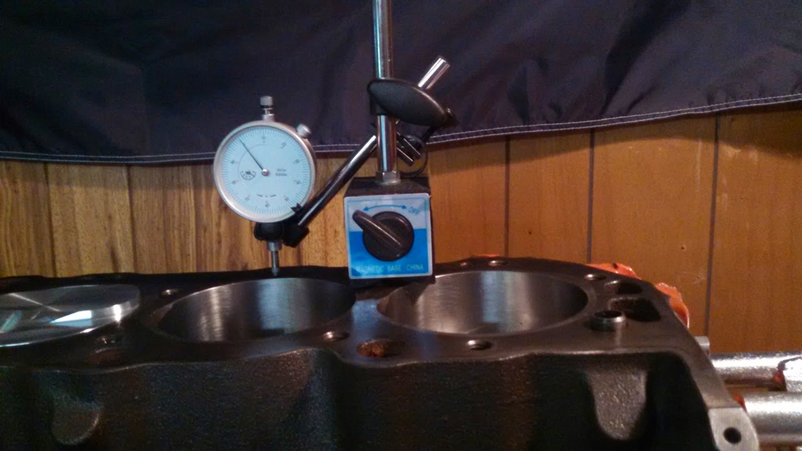
I've made some mention of engine building in previous entries, including some pictures of the bottom end going together, and some discussion of camshaft endplay adjustment.  After the bottom end was together, I was able to make a rough measurement of piston protrusion.  There are better fixtures available for this, but I just used a magnetic base and a dial indicator.

I started by putting the magnetic base on the deck of the block, positioning the dial indicator right next to the cylinder bore.  Then I'd zero the dial indicator there:

Then I'd move the dial indicator over the cylinder and rotate the engine until that piston came to top dead center.

When I first started this, I would then move the dial indicator back to the deck and check the zero on it, and I also tried a few different spots around the piston.  When I felt like I was getting reliable measurements, I moved on and did the rest of the cylinders.

The photo above shows a reading of 0.088", but that actually represents 1.000" minus 0.012", or 0.12" below the deck height.  Everything I measured came in around 0.012"-0.015".  That worked out great, because I read an article which recommended around 0.050" squish area, and the Edelbrock head gaskets advertise a compressed thickness of 0.038", so that puts me right in the neighborhood.

The photo below shows how I positioned the magnetic base and dial indicator in order to measure camshaft endplay.  I used some small machine screws to extend the dial indicator's tip to reach the back side of the camshaft timing gear.


Having determined what thickness head gasket I needed, I went ahead and started assembling the top end.  The photo below shows a head gasket in place, with the ARP head studs also threaded into the block.  Actually, though, I sprayed the head gaskets with Permatex Copper Spray-A-Gasket Hi-Temp Sealant before assembly.


 One head on:

The other head gasket, sprayed with the Hi-Temp Sealant:


Two heads on:


Getting ready to degree the cam, with the degree wheel bolted to the front of the crank:


Rockers and pushrods installed, lash adjusted:


Dial indicator and mag base again, getting ready to degree the cam.


To degree the cam, you have to find top dead center on cylinder 1, zero the pointer on your degree wheel, then find maximum lift for the cylinder 1 intake valve, and compare that to the camshaft manufacturer's spec.  To find top dead center, they recommend that you get a piston stop of some kind, thread it into the spark plug hole, turn the engine until the piston hits the stop, write down the number you read on your degree wheel, then turn the engine in the opposite direction until the piston hits the stop again, write down that number, and top dead center will be halfway between those two numbers.  Well, I didn't like the piston stop much, I could never tell when I was it or not, and I actually ended up bending it.  I decided to take a three-inch-long 3/8" drive ratchet extension, stick that in the spark plug hole and keep my finger on the end of it while I turned the engine.  That way, I could actually feel when the piston touched the end of the extension.

After running through all that, I found that my intake valve was hitting max lift at 105 degrees after top dead center.  If you're not on the spec, there are two alternate keyways in the crankshaft timing gear, one of which advances the cam four degrees, and one of which retards the cam four degrees.  The spec for my cam is 106 degrees, though, so the alternate keyways weren't going to get me any closer.

The photo below shows the locking tabs for the cam bolts folded over to prevent the bolts from backing out.


Because of the aftermarket aluminum timing cover being thicker than the stock stamped steel cover, that meant that the stock stamped steel timing pointer wouldn't fit anymore.  So, I got an aftermarket adjustable timing pointer:


This required locating top dead center one more time so that the pointer could be adjusted to zero.  After I had it set up, I also made a small scratch where the movable pointer bolts to the base of the pointer, continuing the scratch from one piece onto the other.  That way if it ever shifts out of adjustment, I will be able to line up the scratch marks to put it back where it was.

At that point, I decided it was about time to bolt the intake manifold on.  That was pretty straightfoward, except that there were a few bolts that I couldn't fit my torque wrench on to, because of clearance problems.  Fortunately, the bolts took a 3/8" wrench, so it was very easy to get a 3/8" combination wrench, put the box end on the bolt head, and put the open end on a torque wrench to torque the bolts:


The key is to always keep the combination wrench perpendicular to the torque wrench so that it won't throw off the torque value.  If the bolts aren't 3/8", you can put an appropriately sized hex drive ("allen key") socket on the torque wrench and fit your combination wrench on to that hex drive.

Anyway, then I bolted the rocker covers down, put a PCV valve and a breather filter on it, and, wow, this thing looks like an engine again:


One of the last things I did was to finally put the oil pan on it:


In an earlier post I said I was going to re-use the stock oil pan, but later I got to be worried that I hadn't cleaned all the blasting media out of the pan after I blasted it clean.  There were a lot of nooks and crannies that I couldn't reach to clean them out.  So, I looked around online a little bit and I found a cool pan from TransDapt, with an increased capacity sump and wings to keep it low profile, and internal baffles and trap doors to keep the oil pump pickup submerged even under hard cornering.  I'm going to be 100% honest and say the main reason I got it was because it looks like something a racecar would use (which is because it's designed for racing).  The drawback is that the increased capacity is going to mean paying for an extra quart or two of oil every time I do an oil change, but I think I will do an oil analysis to see if I can extend my oil change interval as a result of the increased capacity, too.  The increased interval will offset the increased capacity somewhat, cost-wise, I think/hope.  Also, I do plan/hope to eventually run this car around a race track or autocross course or two, so it can't hurt to have a race-ready oil pan, right?

Anyway, this past weekend was the first one in a long time where it didn't seem like something immediately went wrong as soon as I started working in the garage.  When it was Saturday afternoon and I'd already finished everything I'd planned on doing, I realized that there was still time to do a lot more.

I'm not putting a water pump on the car yet, because I don't know yet if I'll have to use a short pump or not.  Early big blocks had a short water pump, later engines had a long one.  I'd like to use the long one, because it's what was on the engine when it was in the Monte Carlo, and I just like that arrangement better.  But, since the Impala would have had the short pump, I need to find out first if there's clearance for the long pump.  I won't know that until there's a radiator in front of the engine.  Which water pump I use will determine which waterneck I use, so I'm not putting the thermostat on yet, either.  The distributor will go in right before first fire, after I use an old distributor shaft to prime the oil pump.  So, that all adds up to mean that the engine is about as together as it's going to get at this point.

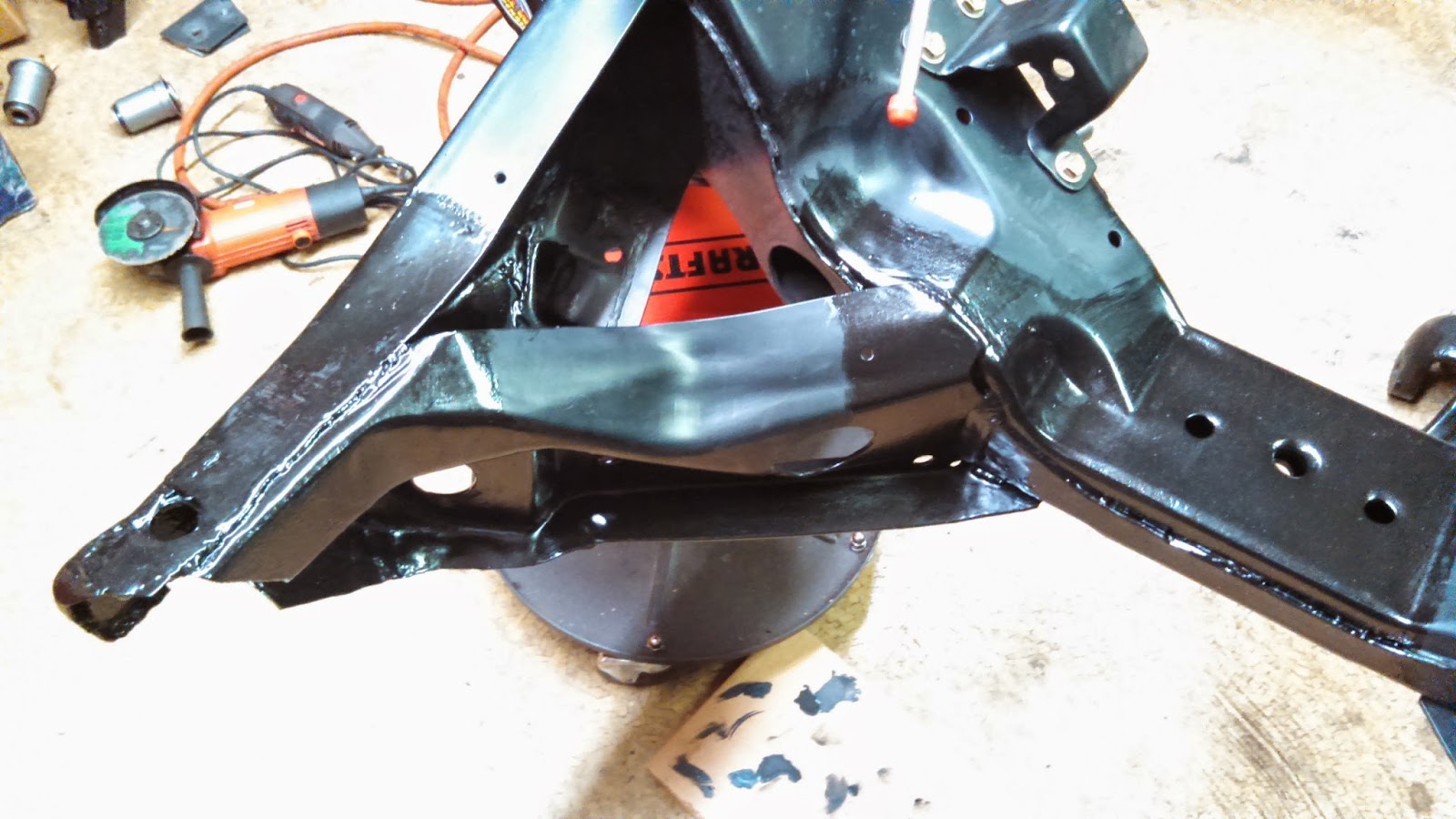
So, I decided it was time to pick it off the engine stand...


...and set it on the frame:


Eagle-eyed readers might notice that in the first of those two pictures, the engine has a flywheel on it, and in the second picture it has a bellhousing block plate on it.  I bolted the flywheel up while it was still on the engine stand, then realized that I had forgotten to put the block plate on first.

Then the flywheel went back on:


Then the clutch:


Then the bellhousing, and the transmission:


This is getting exciting!


Those eagle-eyed readers might notice there that there are a couple of hoses sticking out of the clutchfork hole in the side of the bellhousing.  I decided to use a hydraulic clutch, and those are the bleed fitting and the pressure connection for the hydraulic throwout bearing.

The throwout bearing requires some adjustment to get the proper clearance between the bearing and the clutch diaphragm fingers.  That requires taking the transmission off to adjust the bearing, then putting it on to check clearance.  When I first mounted the trans, I just wrestled it up there.  Confronted with removal and replacement, I decided to make some guide pins to make the job a little easier.  I bought four of the longest 7/16" bolts I could find and cut the heads off of them, then threaded those into the bellhousing in place of the transmission bolts:


This is a common trick when working with big stuff on locomotive engines.  Maybe overkill for this job, but ... hey, why don't you wrestle that transmission around if you think it's so easy?

That gave me something to get the trans started on to line it up and guide it into place.  In the photo below, the tail of the trans is resting on the crossmember of the frame, and the front is sitting on the guide pins.


After the trans was in place, I removed the guide pins one at a time and replaced each one with a bolt as I went.

I ran into one problem while adjusting the throwout bearing.  It has a threaded collar built into it, and that collar rides up against the front of the transmission.  Unscrewing that collar effectively makes the throwout bearing longer, and pushes its bearing surface towards the clutch diaphragm fingers to reduce clearance.  You can only adjust it in full turns of the collar, because the bleed fitting hose has to be at the top of the bearing.  Well, I needed three-and-a-half turns of adjustment, of course.  I thought, "Well, I'll just turn the bearing housing all the way down until it tightens up on the collar, then turn it a half turn so that the collar turns a half turn with it, then back it off to where I want to be."  Well, I didn't really think that through, because after I'd done that the collar had gotten screwed into the bearing body so tight that I couldn't unscrew it.  That was really frustrating and I tried a bunch of hopelessly stupid ideas for unscrewing it before I finally noticed one of my old axles in the corner.  The axles are tapered, so I just pushed the bearing down onto the axle until the collar was jammed on to the taper.  That allowed me to loosen up the collar, then I pulled the whole assembly off of the axle and put it back on the transmission.  When I got it all back together, I was able to put the clearance right in the middle of the spec.

It's always something.

Anyway, it's really exciting to see the engine and transmission sitting on the frame.  I have one more thing to button up on the bellhousing, and that will show up in a future post.  After that, I think it's all suspension work from here until the time when I'm ready to roll the thing back to the body shop.


Friday, September 26, 2014

field work

If you're ever looking to buy an old car, there may come a time when you're talking to a seller and it sounds like they say something along the lines of, "Yeah, the thing was just sitting in a field for a couple years before I found it."  And it will really sound like that's what they said.  But I promise you, that's not what they said.  What they actually said was, "Do not buy this car."

I've recently been considering the possibility of adding a pickup truck to my fleet.  I remember when I was in college, me and my buddy Allen reasoned out that you need at least three vehicles in your fleet:  one to drive, one as a long-term project, and one as a back-up in case your driver unexpectedly turns into a short-term project, or even a second long-term project.

On top of that, I've thought for a long time that there would be some obvious advantages to having a pickup truck.  Right now I have to borrow a friend's truck to do things like taking an engine block to the machine shop, or taking a differential to be rebuilt, etc.  So, because I like old things, and because I like Chevys, I've been looking at old Chevy pickups.  I'm especially taken with the 1961 model.  It's just so ... ugly.  It's hard to resist.

The hardest thing is trying to balance the need for a decent driver against my inner cheapskate and my penchant for what has become fashionably known as "patina."  I went to look at a 1961 out in Schertz a few weeks ago.  It looked real good in the pictures in the advertisement.  It was primered, but appeared to be solid, from what I could see in the pictures.  It also had a straight six, which I thought was cool.

When I showed up, I could immediately see that the truck was not what it looked like in the pictures.  I'm not sure if someone did a crap job of finishing their bondo repairs, or if it was just unrepaired rust bubbling up, or a little of both, but the body looked really bad under the new primer.  Judging from the overspray that I could see, it looked like the engine had been painted in the truck, which implied to me that nothing else had been done to the engine in a while.

I had lost interest before the owner even came out of the house, but I talked to him for a little while anyway.  He said at one point that the truck had been sitting in a field for a while before he acquired it.  He had described his asking price as "firm" in the ad, but as he realized that I wasn't interested, he started dropping it without me even bringing up the subject.  He knocked more than 10% off the asking price in two minutes of casual conversation.  "I want you to have this truck, man."  Not as bad as I want you to have it, sir.

I once looked at another vehicle that the seller said had been sitting in a field.  That was Matilda.  I bought her anyway.  You can see how that turned out in other posts here.  Learning as I go, I guess.  In addition to all the rust damage that had to be repaired on the body and floor pans, some of the bumper mounting brackets were pretty rusted up, and there were some parts of the frame that showed some rust damage, too.

Probably the worst part of the frame is the passenger side front corner, where there appears to be some rust damage, and where the vehicle appears to have also sustained damage from a wreck.  For example, there is a brace that runs diagonally from the frame rail to the front crossmember on that right front corner of the car.  There is a mounting hole that passes through both the frame and the brace, and I noticed a while ago that the two pieces of metal didn't sit flush against each other like they should at that hole.

You can sort of see the gap between the two pieces in this picture:

This recently became an issue when I tried to bolt up some of the aftermarket suspension stuff that I bought.  The stock strut rod is supposed to mount to the frame through that mounting hole, with a big rubber bushing that makes it a little more forgiving of the damage from the wreck.  The aftermarket strut rod that I got has a hard-mounted bracket with a swivel joint and no bushing to flex or wear out.  When I went to bolt that up, I noticed that the lock washer hadn't compressed even though the torque wrench had already clicked.  Then I remembered the damage I'd noticed before and realized that it was causing problems.

When I first noticed the damage, I was hoping that the process of bolting up the strut rod would compress the two pieces of metal together, but it didn't work out that way.  It looked like there was a lot of crud accumulated between the two pieces of metal, so they couldn't pull together even if they wanted to.  So, I stared at it for a while, and then my buddy John said why don't you just cut that brace out, clean out all that crud, and weld it back together.

Well, I wasn't real wild about the idea of cutting up my frame, but the more I thought about the problem, I eventually decided it was the right thing to do.  There were three welds at the crossmember and two long welds at the frame.  I studied it for quite a while and decided I could get at all of them well enough to do the job with a cutoff wheel on an angle grinder.

Here's a view of the brace running from the frame to the crossmember:

And here's a photo from after I cut it out:

And here's a close-up view of all the crud packed in there:

I'm still not sure what it was.  Some of it crumbled away like it was just dirt that had packed in there over time.  Other stuff was a lot harder to grind away, and even looked kind of shiny where I cut into it.  I know that the factory used lead filler in some of their body work, and I started to worry that maybe they used it in their frame, also.  I don't know.  I was almost done by the time that occurred to me, so I just finished up.  Then I went inside and looked up the symptoms for lead poisoning.  Hmmm ... irritability, decline in mental functioning, memory loss.  Well shoot, how am I supposed to know if I have that?  Sounds like just another day....

Anyway, here's a close-up photo from after I cleaned all the junk out of there:

Then I went back and ground away the powder coating to get it ready for welding back together.  The brace would sit nicely in place without anything holding it there, so here you can see how it was prepped for welding:

I figured the best thing to make sure that the strut rod would mount up properly would be to just use the strut rod to hold the pieces together during welding.  So I torqued up the strut rod, and then John came over with his welder and stuck it all together:

A photo from after the welding was finished:

Next thing was to paint it all.  I was planning to use POR-15 again, because it is supposed to give excellent protection from rust.  The heat from the welder looked like it had kind of burned the powder coat in some places, so I went through and ground off any powder coat that looked questionable.  There were some scratches in the powder coat around the middle of the crossmember, so I was planning to paint that, too.  I went over everything that I planned to paint with something like a 120 grit sandpaper, to scuff up the powder coat and give the paint a better surface to adhere to.

This picture is after paint prep:

This picture is from a similar angle to the first picture and shows that the two pieces of metal are now drawn up closer to each other:

And this photo is after paint:

I did four coats of POR-15 semi-gloss black.  On the inside where the two pieces of metal come together, I slopped a bunch of paint in there to try to coat and seal everything as best as I could.

Here's another photo showing how much better the two pieces of metal fit together now:

Not sure why the paint looks green-ish there, trick of the light or something, I guess.  Anyway, this whole deal was an unexpected setback, but I think it looks like a decent and effective repair.

It should be ready to bolt up the strut rod and the rest of the front suspension now.  I think I'm going to need the weight of the engine on the frame to be able to compress the front suspension springs, though, so now I'm working on getting the engine put together.  Pictures of that to come.