Leaving the garage always feels like a bit of plunge, because my driveway is inclined to the point where pushing the car back into the garage is not an option. By the time the wheels pass over the lip at the garage door, if the engine quits, it's probably going to take a piece of equipment to get the car back into the garage. So leaving the garage is something like a metaphorical plunge from the nest, hoping the car is strong enough to fly. Still, there comes a point where there's nothing more to do, no more putting it off.
For the first test drives around the neighborhood, the car still looked a bit like something from a Mad Max movie. I wanted to leave as much external trim off of the car as I could before taking it back to the body shop, to make it easier for them to do their final cut and buff and polish on the paint job, so there was no front bumper, no front grille, no trim around the headlights, etc. But, I also wanted to equip the car with enough equipment to operate it responsibly on public roads, with taillights and turn signals being the main things. For the first test drive, I only planned to drive it around the outside perimeter of the neighborhood park, so I hoped to skate by with some old Illinois license plates. It would probably be equally effective to just go without license plates, but it's always nice to throw the Illinois plates on there, even if it's just temporary. I didn't have any rearview mirrors installed, either, which didn't seem like a big deal until I was actually driving and kept instinctively looking for mirrors to check what was behind me.
A brief sidetrack: a few entries ago, I wrote a little bit about the value of having fun projects to keep myself motivated when I don't feel like working on the practical projects that need to be done. One of those ended up being the dashboard trim, which I worked on a little bit prior to the first test drive. I talked in an earlier entry about how I made a cover plate for the dashboard trim at the far left side of the dash, where I installed toggle switches. Eventually, I got around to installing the rest of the trim across the bottom of the dash.
The long piece at the far right side had some scratches and dings in it. The reproduction pieces are sold as a set for the whole dash, and I didn't want to buy a whole set just to get that one piece. I'd already hacked up and modified some of the other pieces, so no point re-doing that work on new pieces. Eventually I had an idea to cover up the damage with some of the stickers I'd gotten with some of the parts I'd bought for the car. Modern race cars commonly have cameras on board, so every surface that the on-board camera might see is covered with advertising. This was much less common in the '60s, but I took some artistic license and decided to put some advertising on the dashboard trim.
I put on a Holley sticker, an Edelbrock sticker, a Comp Cams sticker, a McLeod sticker, a Hooker sticker, and an ARP sticker. I had to cut them a little bit to fit into the available space, but I really like the look of it. I started out with the modern Holley logo, but eventually I found a sticker based on the old '60s-vintage Holley logo, so I replaced the modern Holley logo with that one. Over the next year or so, I tracked down some other vintage stickers to replace some of the other ones, but the general theme is still there, and is one of my favorite things about the car's interior.

Anyway, I mention the dashboard trim primarily just to set up what you might notice in this video, or this video, both of which were taken during the first drive outside the garage.
The engine rumbles, the transmission whines, there is a lot of road noise with no carpet or other insulation in the car. I remember thinking "this must be what it's like to drive a dump truck," and that thought put a smile on my face. I made a few laps around the road outside the park (making left turns, of course), and back to the garage. Full success. That was a big day.
I was glad I took the video inside the car, though, because during the drive I was actually so busy just trying to adjust to the car's size, the feel of the clutch, the feel of the steering and brakes, checking over my shoulder because I had no rearview mirrors, etc., I never looked at the gauges long enough to notice that the voltmeter needle was jumping all over the place. You can see it in the video, though. I had had a problem with the Corvair's charging system just prior to the time when I drove it to Texas, so I bought a couple spare voltage regulators before leaving. I didn't have a problem, so they sat on the shelf for four or five years. All of my Chevys have used the same voltage regulator part number, so I figured they could come in handy as spares in the future.
I grabbed one of those off the shelf, installed it in the Impala, and that seemed to fix my problem immediately. The original voltage regulator design was mechanical, but at some point through the years, the design was changed to a transistorized version. By chance, the one I swapped in was transistorized, and the one I replaced was mechanical. Based on things I've read since then, it sounds like corrosion on the contacts in the mechanical design can result in the behavior I saw during the first test drive. I eventually discovered that another mechanical spare that I had on hand showed the same erratic behavior, so I guess they both had corroded contacts. So, if you're going to keep spare voltage regulators laying around, I recommend that you buy the transistorized type.
Another issue that I noticed on the first drive was that the turn signal lever seemed a bit short for comfort. The guys at the body shop had recommended an aftermarket steering column, which seemed like a good idea, but the turn signal lever didn't seem to match the size of the steering wheel very well. In an older entry, you can see how the lever extends only a little more than halfway to the outer diameter of the steering wheel. Of course, the manufacturer of the steering column doesn't know what size steering wheel you're going to use, and a lot of people like a smaller steering wheel. But with my hand on the stock steering wheel, it puts my fingertips out beyond the end of the turn signal lever, and I would find myself fumbling for the turn signal lever while driving. With time, I probably would have gotten used it, but I thought maybe I could just extend the lever, instead.
The lever has a knob that threads onto the end of it. I figured maybe I could unscrew the knob, and use some kind of a standoff or something like that to extend the lever's reach. Looking around on McMaster-Carr's website, I hoped to find a standoff with a female thread on one side and a male thread on the other, so that it could just be simply installed between the lever and the knob. I didn't find anything like that with the right thread size, though, so I ended up ordering an aluminum unthreaded spacer. It's basically an aluminum tube, 3/8" outside diameter, 2-1/2" long, with a 0.218" hole through the middle. I cut that to length to get the lever length that I wanted, and tapped the hole to the same thread size as the thread on the lever. The aluminum spacer would now thread onto the lever, so I just needed a way to attach the knob. I bought a bolt with the correct thread size, cut the head off of it, and used it to join the female threads in the spacer to the female threads in the knob.
As always, I made a bit of a mess of it and the spacer got chewed up a little bit in the process of cutting it to length. I used a file and some sandpaper to try to clean up the surface of the spacer, and it came out OK. If you study it closely, you can still see that it's a little dinged up, but if you're not looking for it, it blends in OK.
I didn't take any photos of the individual components, but the photo below shows a close-up of the turn signal lever (foreground), and the smaller lever for the column tilt adjustment (background), and you can see the shape of the spacer installed in the turn signal lever, between the lever and the knob. It doesn't exactly blend in seemlessly, but it does the job, and it doesn't really stand out too badly, either.

One other thing I wanted to do before the car went back to the body shop was to make the blowout straps that I had planned for the back window. In a couple of earlier entries (here, and here), from about a million years ago, I talked about some work that was done to install attachment points around the back window to accommodate blowout straps. I hadn't yet made the straps themselves, though, and I wanted to do that before the car went back to the body shop, just in case I accidentally scratched the paint while fitting them in place. The body shop still had to do the final polish on the paint job, so it wouldn't make any difference if I scratched it before they did that.
The hard part of making blowout straps and fitting them onto the car was figuring out how to attach them, and that was essentially already handled (as covered in those earlier entries). Making the straps should be relatively easy. Early on (waaaaay too early, really) in the project, I had bought a couple thin strips of aluminum that I thought would work OK. They probably would have been fine, but as I thought about it over time, I started to feel like I wanted something a little more substantial. I didn't know if the thinner material might vibrate against the back window due to air flow over the car at highway speed, for example. I ended up ordering a couple strips of three-foot-long, one-inch-wide, 0.075-inch-thick stainless steel from McMaster-Carr. McMaster-Carr is not cheap, but they aren't prohibitively expensive, either, and I love the searchability of their website and their ability to provide seemingly anything.
Cutting the strips to length and rounding the ends off would be pretty straightforward. I figured I could to that job well enough with an angle grinder, even if it might not be the ideal tool for the job. Drilling mounting holes in the ends of the strips would be relatively simple, as well. The main question was how to bend the strips to the desired shape. Looking at old race cars, the blowout straps on their rear windows are often just simple metal straps, secured at the ends and curved over the window glass. But some examples will have bends in them to contour around the trim at the edges and hug the window glass more tightly. I like the look of those, and I'm always eager to over-complicate things, so I thought I would attempt something like that.
So now the question was how to make the bends to curve around the window trim. Putting a bend in a strip of 0.075-inch-thick stainless steel is not hard at all. But making eight identical bends is more of a challenge. The right tool for putting uniform bends in metal is probably a sheet metal brake. But I don't have a sheet metal brake. I've often considered getting one, but they take up more than a little space, and I guess I haven't yet had a project where I really needed one, so I still don't have one. For these straps, I didn't really care exactly how nice the bends looked, as long as they all looked the same. I thought maybe I could build a tool to do the job.
Over the years, I've often read articles, or seen videos, where someone shows how they did a project at home, and they say that you can build what you need with items around your shop. It would always bug me when they would list a bunch of items that I didn't have around my shop. It was also frustrating that I didn't have a shop. So it felt like great progress when I was able to make a small approximation of a sheet metal brake almost entirely from items I had on hand in my garage. I did end up buying a four-dollar door hinge, but everything else was already laying around.

As has become my trademark, it looks like junk. But it did get the job done.
The scraps of metal extending off each side of the hinge mostly just serve as levers. The shape of them is not important, except that they should allow me to work the hinge with some moderate force, and the vertical part of the angle aluminum holds the work piece square to the hinge.
By carefully aligning all these parts the same way each time, you can reproduce identical bends consistently. The last thing to take care of is the angle of the bend, and that's what the carriage bolt is for. The carriage bolt is an adjustable stop, so that you just bend the hinge until it contacts the head of the carriage bolt.
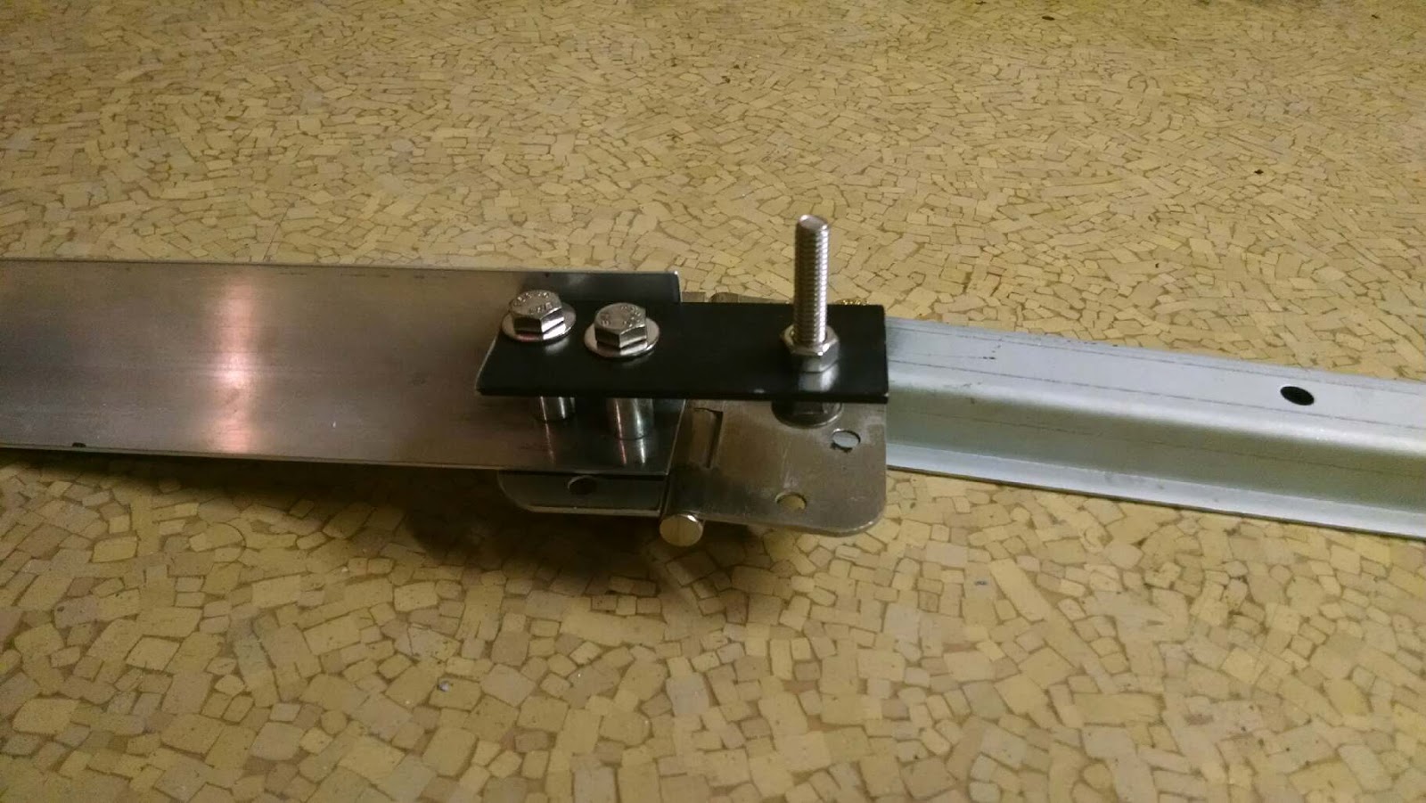

There are two more components, which are one more small scrap of steel, and a C-clamp. The strip of stainless steel to be bent is placed on the hinge, laid alongside the piece of angle aluminum. The flat side of the angle aluminum holds the strip of stainless steel square. When the stainless steel is in the right position, it is clamped to the hinge, using the C-clamp. The small scrap of steel is placed between the C-clamp and the piece of stainless steel, and also held square by butting one of its sides up against the angle aluminum. So the edge of that scrap steel creates a cleaner edge to the bend than what you would get from the rounded edge on the C-clamp's contact point.
The whole thing is a little bit awkward, but by holding the C-clamp vertically in a bench vise, it all becomes a little bit more manageable.

With all that worked out, I got started working on a first strap by rounding off the end of one of the strips of stainless steel, drilling a mounting hole in it, and bolting it in place on the car.

You can see that the square end of the strap is hanging down onto the painted fill panel between the rear window and the trunk lid, which is why I wanted to get this done before I had to worry about scratching the paint.
It would be perfectly acceptable to just cut this strap to length, round off the other end, drill another hole, and bolt it down. But, as I said above, I wanted to do a little bit more than that, to make it look like a more finished piece.
I started by propping the upper end of the strap up off of the glass with a small dowel, to get the spacing I wanted. Then I marked where I wanted the first bend to be, with a Sharpie.

After making some test bends, to set the position of the carriage bolt, and to determine where everything needed to be in order to put the bend in the right place, I felt like I was ready to attempt to make my first piece. After making my first bend, I could measure its angle, calculate how far away an equal-and-opposite bend would need to be in order to get the correct spacing perpendicular to the glass, and then create that bend.

That photo illustrates the basic idea. I ended up deciding that I had started those bends too far down the strap, and it was hanging out over the window a bit further than I would have liked. I ended up scrapping that piece and starting over. After adjusting the position of those bends, and then repeating the process at the other end of the strap, I had a strap that fit pretty well, although I had to do a little bit of massaging and tweaking to get the fit how I wanted it.


Then I was able to relatively quickly reproduce that part, to make a strap for the other side of the window. A little more tweaking and fine-tuning, and I was essentially finished.

I am pretty happy with the results. I pulled the straps off before taking the car back to the body shop, so that they wouldn't be in the way while those guys were doing the final polishing on the paint.
Indulging one last impulse to over-complicate things, I added some gasket material under the contact points of the straps before I installed them for the last time. I didn't want the stainless steel straps in direct contact with the paint and glass, so I used an adhesive to hold some fibrous gasket material in place.


I also put some thread-sealer on the bolts when I installed them, to try to keep water from collecting in the bolt holes. The Sharpie marks washed off with Brakleen, but there was some discoloration from where the metal got hot during cutting, so I used some sandpaper to take off that surface discoloration. There were also some marks left from the forming process when the strips were produced, so I just went over the whole surface with sand paper to try to create a more uniform, light "brushed" look. Anyway, I guess by that time I had run out of ideas for how to further complicate things, so it was pretty much "job done" at that point.
There were a few other little things that I wanted to do before I drove it up to the body shop, but it was pretty much ready to go. One of the last things I did was to put in a clutch pedal stop. When I first installed the clutch master cylinder, my plan was to make the geometry of the pedal linkage such that pushing the pedal to the floor would use the full stroke of the piston in the master cylinder. That worked out fine, except that I later read that, if you install an aftermarket hydraulic clutch, you really need to put in a pedal stop so that you won't put excessive force on your clutch. I guess this is because the master cylinder can be matched to the throwout bearing (or slave cylinder) such that a full stroke of the master cylinder gives a full stroke of the throwout bearing, but they don't know what clutch you're using, so a full stroke of the throwout bearing might be excessive travel for the clutch. For this reason, a pedal stop should be installed, so that you don't push the clutch fingers past their intended point of operation. Otherwise, "damage may result," as the paperwork often says.
The more you learn, the more you realize you don't know, and I found out about all this pedal stop stuff right around the time that I was doing all this other work. One possible failure mode, if you don't have a pedal stop, is for one of your hydraulic components to fail and leak all your hydraulic fluid out, and then your clutch doesn't work. I actually thought I'd learned all this too late after I found a puddle of oil right under the bellhousing after having completed a couple of test drives around the neighborhood. I thought the throwout bearing had failed a seal and leaked hydraulic fluid onto the floor. That would have required pulling the transmission to replace the throwout bearing. Fortunately, it turned out that one of the rocker covers wasn't sealed well, and the puddle was just engine oil that had run down the side of the engine, down the side of the bellhousing, and onto the floor. Phew.
A lot of pedal stops seem to be mounted on the firewall, such that the pedal will contact the stop at the end of its travel. I didn't really want to make more holes in the firewall if I could avoid it, and I was kind of running out of real estate in that area, anyway. There were already a couple of unused bolt holes drilled through the pedal arm from my first failed attempt at mounting the clutch linkage, so I thought maybe I could use those to mount something on the clutch pedal arm, and that could contact the firewall at the end of the pedal's travel. The simplest thing I could think of was to make a bracket out of a piece of angle iron, so that I could mount a carriage bolt that would be pointed at the firewall. I already had a pretty stout piece of angle iron laying around, so I cut that down to what I wanted and put some holes in it.

The two holes are used to bolt it to the pedal, and a long carriage bolt passes through the single hole, with a nut on each side to hold it in place. That way, the pedal travel can be adjusted by adjusting the position of the carriage bolt.


That all worked out pretty well. The directions I found for adjustment said to find the point where the clutch engages/disengages by jacking one driven wheel off the ground and operating the clutch pedal with the car in gear while someone tries to turn the wheel by hand, then to set the limit of the pedal's travel about a quarter inch past that point of engagement. Like I said, I was running out of real estate on the firewall, and this adjustment was complicated somewhat when I tried to set the proper travel and the head of the carriage bolt landed right on the head of one of the bolts for the brake booster. That held the pedal too high, but when I tried to adjust the carriage bolt to allow the pedal to travel further, then it would miss the other bolt head and the pedal would drop too far. I messed around with it a few times and finally thought I got it adjusted to where the travel was correct. BUT...
...fast-forward to the future, and after I got the car back from the body shop, I was having trouble getting used to the clutch operation. It felt like it was sticking, or hanging up, at the bottom of its travel. When I took a look down in the footwell to investigate, I found that the carriage bolt was deflecting just enough for the edge of its head to pop past the head of the bolt for the brake booster. So, the pedal stop was "latching" onto the other bolt, in effect.

So each time I released the clutch pedal, I had to take off enough force for that bolt head to pop loose, but then the pedal would want to spring up rapidly and I'd have to "catch" it before the clutch engaged. It's a very awkward way to try to operate a manual transmission. I solved the problem by removing the carriage bolt and grinding down the outside diameter of its head until it would clear the head of the other bolt. Things seemed to operate smoothly after that.
The only other major thing I wanted to get done before taking the car back to the body shop was a front-end alignment. Alignments aren't cheap, and I don't like to hand my keys to someone else if I can avoid it, so I decided to try out one of these do-your-own-alignments-at-home deals. These can cost upwards of $400, depending which one you get, but an alignment is probably going to cost over $100, so it doesn't take long to justify the cost, if the tool works. I found one for just over $200 that seemed to have all the important features of the more expensive ones. I was really glad that my buddy Allen came down to help me with it, because it's a tedious process that I think would have been even more tedious (although not impossible) if I was doing it by myself. The kit seems to work pretty well, though, and the results seem to be repeatable. I have ended up adjusting the toe-in several times, and I have been pleased with the results. The measurements seem to be consistent and predictable.
Anyway, at that point I couldn't think of any more excuses for not taking it back to the body shop, so I stopped by one day to see if they had any floor space for me. I was kind of surprised they even recognized me when I walked in, considering it had been almost two years since the last time they saw me, and I assume they had had more than a few different people come through in that time. But, they gave me a warm welcome and we all stood around for a little while and I told them about the stripped head bolt hole in the engine block, and pulling everything apart again, and they winced and made noises like they'd been through that kind of thing before, which made me feel better. There are a lot of reasons why I'm glad I took the car to a body shop for the paint and body work, but probably the best thing about it has been these times when the conversation takes a turn where I feel like they're relating to me as if I'm one of them, and not just a customer. There are so many times when I feel like I'm flailing around in the garage, feeling like I don't know what I'm doing and I'm fouling everything up, so it's really satisfying, and kind of reassuring, to talk to someone who does that work for a living, tell them about something that went wrong for me and I thought maybe I screwed it up, and have them just laugh and say something like, "Oh, yeah, that's the way it always goes," or something like that. Anyway, they said they had room for the car whenever I wanted to bring it, so we made a plan that I'd bring it up the next Friday.
I was pretty nervous, driving it up there. There was no reason to think that anything was going to go wrong, but it was just the unknown of not having driven it that far before. I packed a toolbox full of everything I could imagine I might need, and I wore clothes that I wouldn't mind laying on the side of the road in, in case I had to crawl underneath the car to try and fix something. The car still had no grille, no front bumper, no trim around the headlights, no interior carpeting, etc. I checked the traffic before I left, and there was a wreck on 410 that had traffic backed up, so I took I-10 to 35 instead, which added a little bit of mileage to the trip but kept me out of traffic pretty well.
All in all, the trip went fine. As soon as I got on I-10, I had a couple flashbacks to Bertha. First off, the Impala is just such a big car, and the seating position is so different from what I'd gotten used to in the truck, it just felt kind of uncomfortable to drive, like every part of the car was about to scrape on everything around me. It reminded me of the first time I test drove Bertha on 290 and it just didn't feel like there was enough room on the interstate for so much car. Driving the Impala to the body shop, I realized that I was way over on the left side of my lane, because the car just felt so big that I was leaving way too much room on my right. I think you can see Jay Leno doing the same thing, hugging the dotted line, at the beginning of this video about one of Steve Strope's builds that I like a lot (I've linked to this video before, in another entry, but I like this car a lot, so why not another link).
The other thing that reminded me of Bertha was just the heat from the engine. With no carpeting, nothing to close off the fresh air vents, and no other interior to speak of, there was a lot of heat from the engine making its way inside the car, and it reminded me of driving the Monte Carlo on hot days, pulling up at stop signs and a cross-breeze would carry a bunch of heat from the headers up through the open window. Thinking about that made me realize, this was Bertha's engine (block, at least), and this was the first time I'd driven it in over five years. That was pretty cool to think about, being "reunited."
Anyway, the car made it up there, some 30+ miles. I discovered a few things on the drive up there that I knew I'd have to fix later, but she made it up there without any significant trouble. I stood around with the guys at the shop while they looked over what I'd done and commented on a couple things they liked, which was nice. Obviously, just getting the car up there was a major milestone for me, and I was excited knowing that the project was about to make a major leap forward as they completed their work. More on that, still to come.
I took some pictures while I waited for my buddy Allen to come pick me up.