Thursday, March 12, 2015

stuck in painting Hell

I love to order car parts.  The project is frequently derailed by various problems, which can be something as small as realizing that I still haven't ordered some part and now I need it, or something more complex, like realizing that there are a lot more complications to installing a roller cam in an old non-roller engine than I ever originally thought, or trying to figure out how to get my headers up off of my steering box.  In any case, trying to find the right part to solve a problem or fit an application can be like a puzzle combined with a scavenger hunt.  And it's really amazing how long those puzzles and hunts can take in a lot of cases, even for the ones that seem simple.  I love Summit's website, though, because they make it so searchable.  You can sort and filter the results of a search in so many ways, it can lead you to things that you didn't even know existed, but which might be just what you need (or at least want).

The best part of the process, though, is the feeling of having just ordered a part.  At that point, the puzzle has been solved, the project is back on track, if somewhat delayed, and all you have to do is sit back and wait for the part to arrive.  Then the part shows up and it's like Christmas.  Then the part doesn't fit, and ... well, let's not think about that right now.

When I ordered an oil pan, I sorted by my engine type, my car type, and by orange paint, because I wanted it orange, and I didn't want to have to paint it.  I also picked this specific pan because it has a custom-fabricated enlarged sump with an internal baffle to control sloshing and keep the oil pickup submerged.  That's all "race car stuff" that I don't really need at all, but which I think is neat, and is not prohibitively expensive, so I'm going to have it.

Unfortunately, as I mentioned in the last post, I had to pull the engine back off the chassis due to an interference between the oil pan and the steering linkage.  The larger sump (which I don't really need) interferes with the center drag link in the steering linkage.  According to the information listed on Summit, the pan was supposed to fit my application, but when I put it all together, there was just a very slight interference when the wheels were turned all the way to one side.

Part of the problem was probably that I had installed aftermarket control arms, and a disc brake conversion kit which required modifying the steering arms, and all of this may have contributed to changing the geometry of the steering linkage.  It may have been further complicated by the fact that the steering box on the '65 Impala is mounted behind the front wheels, which puts the steering linkage between the oil sump and the chassis crossmember.  Bertha, my 1972 Monte Carlo, had the steering box mounted in front of the front wheels, which puts the steering linkage in front of the crossmember and nowhere near the oil sump.  Same goes for a Chevelle, which is probably a much more popular application than a 1965 Impala, so less likely to generate complaints to the manufacturer of the pan.

In fact, 1965 Impala projects seem to tend to be of the type that get either a stock oil pan, or maybe a chromed stock oil pan.  It's possible I might be the first person to ever put this particular style of oil pan on a big block in a 1965 Impala.  Who knows.  In any case, the oil pan and the center drag link want to be in the same spot, and that's no good.

So, I pulled everything off the chassis and put the engine back on the stand.  As received, without modification, the front of the sump was pretty much just a vertical wall.  I didn't really get any pictures of it before modification, but you can kind of see it in this picture from the Summit website:


The interference was so slight, I originally thought maybe I could just bend the front of the sump to form a "pocket" that the centerlink could tuck into when the wheels were turned.  I didn't want to cut up the pan and then have to get it welded back together if I could avoid it, so I decided to try smashing it with a hammer, instead.

Before I pulled everything off of the chassis, I marked the vertical centerline of the centerlink on the front of the oil pan.  After I had everything apart, I took a section of an old jack handle and used a couple ratchet straps to clamp it on to the front of the sump.  I put some masking tape on, too, in a foolish hope that maybe it would keep me from messing up the paint job too bad.


Once I had that all set up, I pretty much just started whaling away on the jack handle with a hammer.  The next couple pictures show how the front of the sump started to cave in to form the desired pocket.  I tightened the ratchet straps as necessary to hold everything together.


Of course the paint was pretty messed up, so I did have to re-paint the pan at that point.  Good thing I ordered an orange one, so I wouldn't have to do that.

After mashing and painting:


Re-installed on the engine


So then everything went back on the chassis.  The centerlink tucked up into the pocket nicely.  There was probably still less clearance than I should have had, but I decided it was good enough, and I pressed forward.

At some point, I decided it was probably time to think about mounting the exhaust headers.  After wrestling one header up into position, I found that it was going to be impossible to install the headers, because the mounting flange interfered with the nuts on the cylinder head studs.  The stock cylinder head bolts sit relatively flush to the cylinder head, whereas the aftermarket studs that I decided to use stand up a little bit taller.  Why do I need studs?  I don't, I just decided it would be cool to have them.  When you start talking about bolts vs. studs, everyone mentions that if you use studs, you'll have to remove your brake booster if you want to remove the heads with the engine in the car.  Nobody mentions that your header flange will hit them.  But in my case, it did.

I figured I must not be the first person to have this problem, so I started doing some research online.  A lot of people talked about installing bolts for the row of fasteners below the header flange, and using studs for all the other cylinder head fasteners.  I didn't really want to backtrack and re-torque the cylinder heads, and I didn't want a mix of studs and bolts, so I kept looking around until I found some big block Chevy guys who said they'd just clearanced the flange with a grinder.  That was what I really wanted to do, I was just doing research to see if there was anyone who said, "Here's why you should never do that...."  I didn't find anyone who said that, so I decided to do some grinding.

(I am a little bit worried about how thin this makes the flange at the notch, and I wonder if they're going to crack/break there, but I couldn't find anyone else who mentioned problems like that, so ... I guess we'll just find out.)

The basic shape of the header flange repeats at each exhaust port, so I just traced one part of it on to a piece of cardboard, then I cut that out, put bolt holes in it, and then cut it a little bit at a time until it cleared the stud and nut:


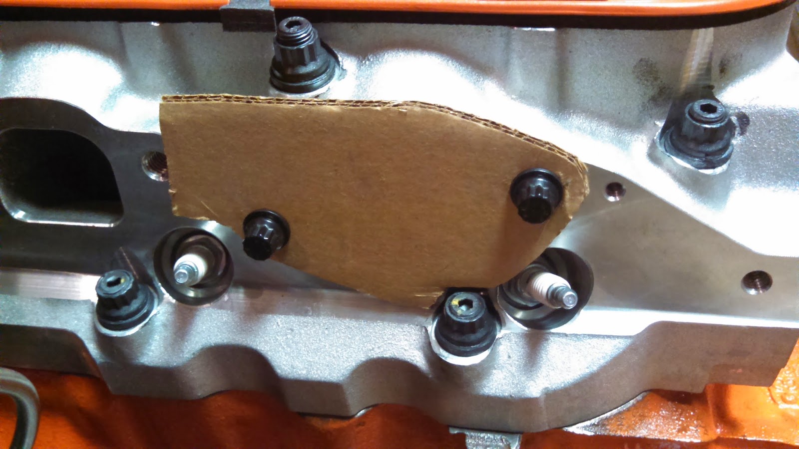
I used that as a template to transfer the shape of the notch on to the header flange, then I cut the notches with an angle grinder.  These two pics show a "before" and "after" comparison (the flange is upside down in these pics, so the notch is at top right in the second pic):


Test fit:


After cutting the flanges, I had to re-paint the headers.  I ran a piece of string from the track for the garage door opener, down through the header bolt holes, up to the garage door track, and down to a cabinet handle that I tied it off to.  That allowed me to balance the headers on their outlet flanges, so I could paint all the way around them in one shot.


Once that was done, it was right back to the action.  Certainly, there was nothing that could stand in the way of a smooth and successful completion of the project now.

I went to install the headers on the engine, and immediately found that the driver side header was interfering with the steering box.  Now, these headers are supposed to be specifically for this engine, in this car ... maybe some false information has been distributed to the aftermarket regarding the exact location of the 1965 Impala's steering box...?


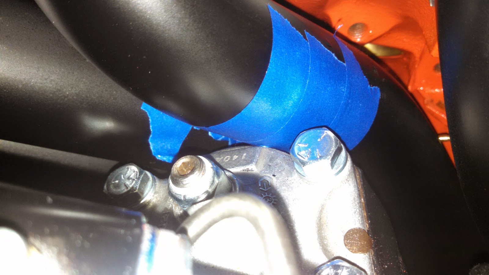
It's hard to get a picture that really shows exactly where the interference is, but it seemed to be pretty slight.  The cover on top of the steering box there is aluminum, and looks to be really beefy, so I thought maybe I could just file off some of the beef to create some clearance.

If you watch TV shows about car projects, or read magazine articles about car projects, or pay attention to car projects at all, you've probably heard a story about a problem with header clearance.  It seems to be a commonly accepted "fix" to just put a dent in the header primary to create clearance, but I've always hated that solution.  It seems like you're just "solving" one problem by creating another.  Still, a lot of "pros" seem to think it's OK.  But I didn't want to do that, and I figured that if I did do it, then I'd have to give up my right to complain about other people doing it.  I don't know if taking a file to the steering box cover is really any better than putting a dent in the header primary, but ... in my mind it was, I guess.

I had the engine on the hoist and not resting on the engine mounts as I was doing all this.  I'd hoist it up a bit, file some, and then lower the engine to check clearance.  Every time I lowered the engine, though, it just dropped right through all the clearance I'd created until it was resting on the steering box again.  Apparently I was off by more than I thought.

A portrait of the artist as a guy trying to figure out why his headers are all over his steering box:


OK, so now a story about engine mounts.

I decided to start by calling Hooker Headers, to see if they had any comments about what my problem might be.  They asked if I was using big block mounts or small block mounts.  I told them I don't know.  There is a lot of interchangeability of parts, by design, in the engine mounts, and I don't really know what I have.  I know there are a couple different styles of mounts, but I've never been able to get a definitive answer on what the different styles are supposed to be for.  Part of the reason I got what I got was because the frame already had frame mounts on it, so I just looked around until I could find a set of engine mounts that would mate to the frame mounts.  I suspect the car originally came with a small block, so those frame mounts may have been intended for use with a small block, but I don't really have any way of knowing any of that for sure, either.  The VIN only identifies it as an SS V8 car, it doesn't code the specific size of V8.  Anyway, I started looking around online to try to find out, what is the big block style, what is the small block style, and for the different types of mount that I'm aware of, are there any dimensional differences that would affect the position of the engine once it's mounted?

The answers to those questions ended up being, "I don't know," "I don't know," and "not that I can tell."  But while I was searching around Summit looking for all this stuff, I stumbled on to something I'd never heard of before:  engine mount shims.  There were three or four different companies selling 3/16"-thick shims that could be bolted in between the engine mount and the engine block.  At the angle that the mount is bolted up, this 3/16" shim effectively raises the engine up about 1/4" vertically.  I thought that sounded better than dented headers, so I ordered a set of those, AND ... longer bolts, of course, so that the bolts would reach through the shims to bolt up the mounts.

After wrestling around with the headers and trying to create clearance, I'd knocked some paint off of the headers.  The shims were unpainted as received, so it was time for more painting.


Notice that this time I hung the shims on the string in between the headers, so I could paint all sides of all things at the same time.

Of course, those of you paying close attention will be saying to yourselves, "But wait a minute, if you had knocked that pocket into the oil pan to accommodate the centerlink, and now you're shifting the pocket up a quarter of an inch, doesn't that mean that your pocket is in the wrong place now?"

Yes.  Yes it does.  It means exactly that.  So, once again, the engine came back off the chassis, and the oil pan came back off the engine.  And it was clear now that it was going to have to be cut.

To be honest, I wasn't really sure exactly how this was going to work as I started cutting, but I started by going across the front of the bottom edge.  I did all the cutting using a cutoff wheel on a Dremel.


Then I cut up the seams where the flat front angles back.


I started to try to bend the bottom flap up a bit, but it didn't really want to bend where I wanted it to bend, so I went back and kind of "scored" the line where I wanted it to bend.  I was still using the Dremel cutoff wheel for this, but I just didn't cut all the way through.


It seemed more ready to bend now, but I cut a couple little pie slices at the corners to provide clearance for it to swing through that area.


That allowed me to fold that lower flap under everything else.


A different angle to show the same stage:


Then I went across and trimmed off the upper flap, trying to keep it tight with the other flap.


Skipped through a few steps without photos, but basically folded the ears over at the ends and trimmed them off flush with the other flaps, then ground off all the paint to get it ready for welding.


A technician at work welded it up for me, including running a bead down the scored line at the lower edge.


Good thing I ordered it orange, so I wouldn't have to paint it.

Next, I filled it with some old, used oil, and put it on the floor on top of some clean paper towels.  This was my leak check.  I let it sit there for a few days, and didn't find any leakage.  So, I drained out the used oil, and then very carefully and thoroughly cleaned out the pan with Brakleen, trying to make sure to clean out all the debris that went into the pan when I cut it.  And then it was time to paint it.

So, I painted it, but somehow this time I didn't manage to get the top side of the "wings" painted.  And you could see that pretty clearly, and it looked bad, so I decided I'd paint it again.  I've had bad luck in the past with spray paint flaking off, so I've been trying to follow all the directions on the can, and the can says that once the paint is dry you're supposed to allow a week of cure time before putting on more coats, so that was a week lost.  Good thing I ordered it orange, so I wouldn't have to paint it.

But wait ... it gets better.  The next time I painted it, the paint was dry and I picked it up to look it over, and it somehow slipped out of my hand and fell on the floor, which knocked the fresh paint off a couple corners.  Maybe I subconsciously don't even want this pan painted?  So I painted it one more time.  After waiting another week.

But wait ... it still gets better.  The can also says that it is "EXTREMELY IMPORTANT" to bake parts painted with high temp engine paint at 200degF for one hour, to finish the curing process and get full resistance to chemicals and all that.  How do you bake an oil pan?  Well, you put it in your oven.


But then you can't close the door on the oven, so you make an "oven extender" out of a cardboard box coated in "Great Stuff" insulation.


 Is it smart?  Ohh ... probably not.  But it actually worked pretty well.  The box on the floor under the oven door is a digital multimeter connected to a thermocouple which is reading the temperature in the box, to make sure it's getting hot enough in there, but not too hot.  There was a lot of nervous monitoring of the process.  The paint is supposed to be cured at 200degF, but the insulation warns that it will ignite at 240degF, so you have to be very careful, but it is workable.  I know because I did it four times.  Good thing I ordered that oil pan in orange so I wouldn't have to paint it.

So, the part where it gets better is that after I painted the pan for what I thought was the last time, I baked it again, but for some reason this time the paint bubbled up all over the bottom of the pan.  I'm still not sure why that happened, but it looked like junk.  I tried to sand it down, but that just knocked all the bubbles off and left big "holes" in the paint all over.  It looked terrible.

At that point, the pan had been painted by the manufacturer, then painted after I deformed it, then painted after I didn't get complete coverage, then painted after it was cut and welded, then painted again after I dropped it.  It had at least five coats of paint on it.  I was so sick of messing with the stupid thing, I thought about just giving up and putting the stock pan back on.  But I also had so much time in the stupid thing at that point, I wasn't ready to just cut bait and walk away.  I decided to just remove all the paint and start over.

To remove the paint, I used something like a 40-grit paint and rust removal wheel on my angle grinder.  Although, I've gotta say, I really think the manufacturer of that wheel is selling his product short.  It says it will remove paint and rust, but I accidentally tagged my knuckle with it once, and it turns out that it removes skin and flesh pretty effectively, as well.

Anyway, I got the pan cleaned up pretty well, then sprayed it with a high temp primer, then sprayed it one more time with Chevy orange.  Baked it.  All done.

But wait ... as I pulled it out of the oven, I noticed one corner that had apparently been scraped on something, which knocked the paint off of it.  After a lot of cursing, I decided that I would try one more time, and whatever came out of the oven next would just have to be good enough.

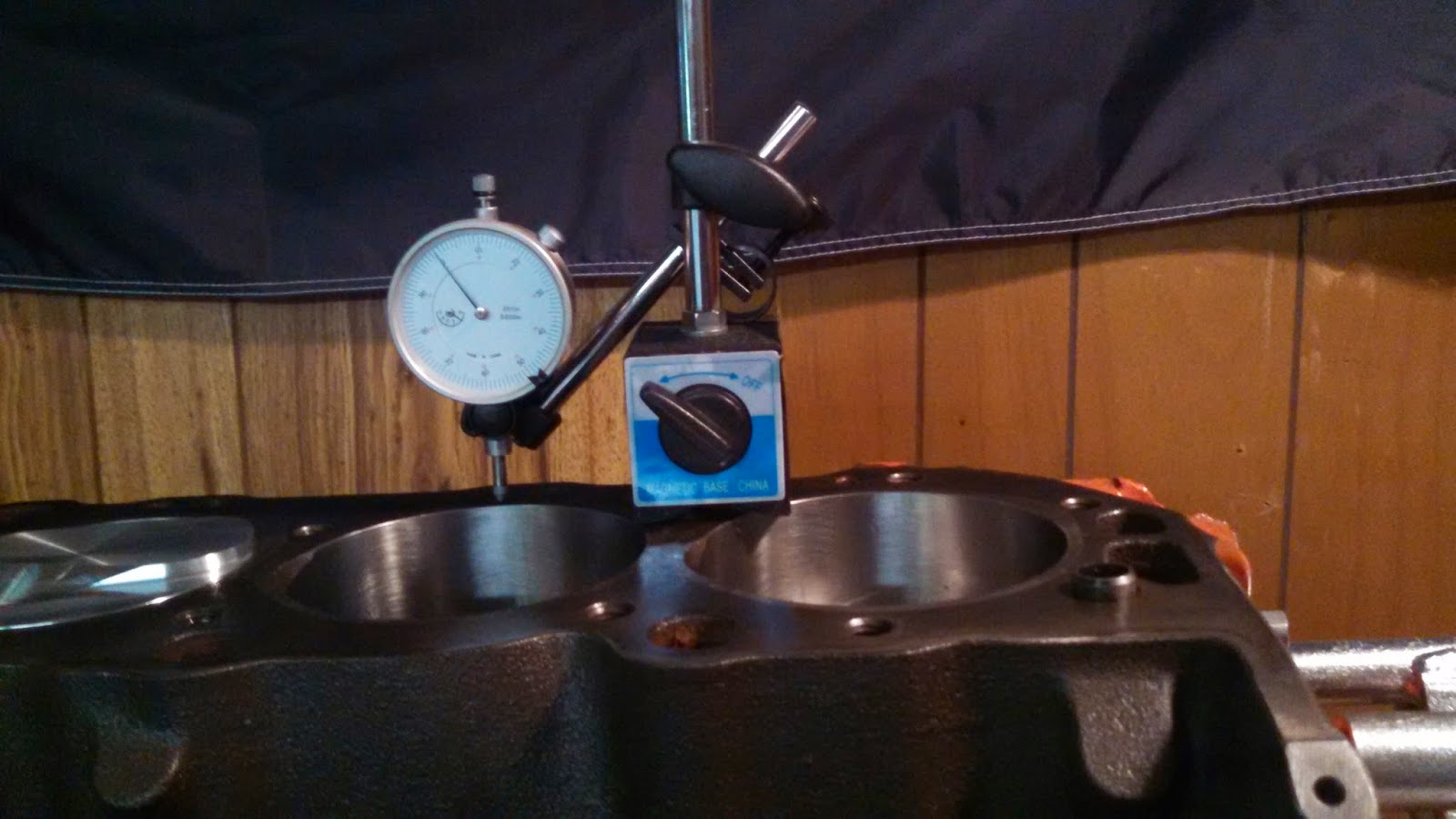
So, I painted it one more time, handled it VERY CAREFULLY ... waited a week, then baked it to finish the curing process, and ... it finally came out good.  Below is a side view to show how the front of the sump, which used to be a vertical wall, now slopes back at an angle for additional clearance.


Back on the engine:


In this photo you can also sort of see the engine mount shim, in between the engine block and the engine mount:


Starter motor is mounted there, too.

So, as you can see in the photo two photos up, I decided to put the headers on the engine while it was on the stand this time.  I wrapped old t-shirts around anything that the headers might bump into as the engine was being lowered on to the chassis, and I dropped the whole deal down into place.  Plenty of clearance in front of the oil pan now, looks like almost a full inch.  And between the header primary and the steering box, maybe a quarter inch.  I'll take it.

This isn't all that's been going on, there's also been tremendous amounts of cursing that I didn't mention here.  And I've also been doing other work on the car.  And that will be detailed here, too ... eventually.


Monday, December 15, 2014

Let it Bleed

Part of the reason I don't update this as often as I'd like is because I like to be able to summarize a part of the project from start to finish, and sometimes it just seems like I can't finish anything.  There are a lot of open issues right now, even though it feels like the chassis is almost ready to send back to the body shop.

One thing that I did finish was to make a block-off plate for the clutchfork window in the side of the bellhousing.  Because I'm using a hydraulic throwout bearing, there is no clutch fork in my setup, and the window where the clutch fork would pass through leaves a gaping hole in the side of the bellhousing.


I decided I would prefer to close that up, so I made a block-off plate.  I got a piece of steel from Lowe's, 3-in. wide and 3/16" thick.  I cut off a length of it, and started trying to shape it to cover the opening in the bellhousing.  First I bent it to curve from the side of the bellhousing around the back of it.  But, where the back surface of the bellhousing is flat, the side of it is curved.  To try to match the curve of the side of the bellhousing, I laid the edges of the side of my cover on the open jaws of a bench vise and started hammering the inside of it.  I was actually very surprised by how effective this was in shaping the cover to fit the bellhousing.

However, where the cover curved around the side of the bellhousing and transitioned from a flat surface to a curved one, it left large gaps along the sides of the curve.  To try to close up those gaps, I cut slots into the sides of the cover, and folded the sides in to close up the gaps.  At this point things were looking good enough that I decided to take a couple pictures:


You can see that I had already rounded the corners of the back side to clear the mounting ears of the transmission.  If you look at the pictures of the bellhousing above, you can see that I had also already drilled and tapped some mounting holes for the cover.

The cover wasn't quite wide enough to put bolt holes in it.  I couldn't find a piece of steel that had the thickness I wanted and sufficient width for bolt holes.  So my plan was just to notch it for the mounting bolts.  I notched it and made a test fit:


Not too bad.  I was honestly amazed at how well this thing was coming together.

So, there are two hydraulic lines to the hydraulic throwout bearing.  One is the pressure line wihch actuates the bearing, and the other is the bleed line.  I needed to make a couple holes for these lines to pass through.  I checked to see where the lines "wanted" to run to, and then drilled holes in those locations:


A technician at work volunteered to weld up the cuts that I'd made in order to shape it:


Next I painted it.  I used POR-15 for rust prevention, as I have on so many other things with this project.  Actually, I painted it, then I found out that one of the bolt notches wasn't in quite the right place, so I wallowed it out a bit.  Then I painted it again, and then I found out that the steel was a little too thick for the grommets that I wanted to use to seat properly.  They kept wanting to pop out.  So then I beveled the edges of the holes, to create a thinner surface for the grommets to grab.  Then I had to paint the cover again.  I was applying the last coat of paint when I dropped the darned thing on the floor, right into a pile of steel dust under the bench grinder.  This resulted in quite a bit of cursing, but I decided it wasn't important enough to clean it all up and re-paint the cover again.  I just wiped it off as best as I could and then finished applying the last coat.  As a result, the cover now has a bit of "texture" to it.


I had some grommets that I was able to stretch enough to get them over the fittings on the end of the hydraulic lines:


Everything went together pretty well for the final installation:


After all that, I started putting the front suspension together.  After the front suspension was installed, I mounted the steering linkages.  When I had the centerlink in place, I could see that the clearance between the centerlink and the oil pan was pretty small.  With the wheels turned all the way to full lock, there was a slight interference between the centerlink and the oil pan.  I decided I'd better pull the engine back off the frame, pull the oil pan, and do something to create some more clearance.  More on that later.

While I had the engine and transmission off the frame to mess with the oil pan, I also decided to do a little more work on the hydraulic throwout bearing stuff.

First, a photo of the inside of the bellhousing, with the cover plate installed.  Here you can see the throwout bearing in red, and the two hydraulic lines running out through the cover plate:


When everything is finally installed on the car, there should be a hard hydraulic line running to the pressure line, and that will keep that line from hanging free and flopping around.  But the bleed line won't be attached to anything.  While I had everything apart again, I decided to make a clip to hold the bleed line in place a little better.

I went back to Lowe's and picked up some stuff that looked like it would do the job.  I got a clip to hold the line, a long bolt, a steel spacer, and a couple of nylon spacers that fit perfectly inside the steel spacer.


The steel spacer was oversized compared to the bolt, so I put the nylon spacers inside the steel spacer and drilled out their inside diameter to fit the bolt.  I checked to see roughly where I wanted the clip to go, then I drilled and tapped a hole for the bolt in the side of the bellhousing.  The clip was a little bit oversized for the hydraulic line, so I removed the rubber that was on the clip, and replaced it by wrapping a piece of rubber hose around the hydraulic line.  This all worked out pretty well.  Photos of the final installation below.


Like I said, there are a few open issues that I still need to finish up before the chassis goes back to the body shop.  These include the oil pan/steering clearance, exhaust header installation, and finishing front and rear suspension installation.  Also probably some things I don't know about yet.  More on all of that still to come.


Thursday, October 16, 2014

Prime Mover

When I was in college, my senior design project was to (working in a small team) design and build and mount all the electrical and electronic components for the Formula SAE team's car.  There were other teams assigned to other subsystems of the car.  Once a week, we all got together to give a presentation on our progress.  About halfway through the semester, I started to realize that we were the only team that had to come through on all our deliverables in order for the car to run.  The engine team, for example, would say, "We designed this great intake manifold, but we're not going to have time to get it made, so this year's car will run with the stock intake manifold.  Maybe the manifold we designed will be for next year's car."  A month or so before the end of the semester, one of the professors asked me how we were coming along with the electrical systems.  I told him, "Gee, I don't know, electrical systems might have to end up being something for next year's car."  He was not amused.

Another thing that differentiated our team from the others was the format of our presentations.  The other teams all used fancy powerpoint formats with official university logos, and their slides were crowded with colorful graphics of car components and eye-catching animations.  We prided ourselves on our spartan presentation.  We used a generic powerpoint format and simple bullet point text, except where illustration was of practical value.  A member of one of the other teams commented on this once, and I (half-) joked, "You don't need all that extra stuff when you've got actual content."  He laughed and (half-) joked, "Oh, I wouldn't know anything about that."

(He is, to be fair, probably a vice president somewhere now, I'd guess.)

Anyway, this is all an unnecessarily elaborate introduction to recognize that these entries sometimes lean heavily on unnecessarily elaborate prose to fill in the gaps between actual content.

But this entry will show that you don't need all that extra stuff when you've got actual content.

I've made some mention of engine building in previous entries, including some pictures of the bottom end going together, and some discussion of camshaft endplay adjustment.  After the bottom end was together, I was able to make a rough measurement of piston protrusion.  There are better fixtures available for this, but I just used a magnetic base and a dial indicator.

I started by putting the magnetic base on the deck of the block, positioning the dial indicator right next to the cylinder bore.  Then I'd zero the dial indicator there:

Then I'd move the dial indicator over the cylinder and rotate the engine until that piston came to top dead center.

When I first started this, I would then move the dial indicator back to the deck and check the zero on it, and I also tried a few different spots around the piston.  When I felt like I was getting reliable measurements, I moved on and did the rest of the cylinders.

The photo above shows a reading of 0.088", but that actually represents 1.000" minus 0.012", or 0.12" below the deck height.  Everything I measured came in around 0.012"-0.015".  That worked out great, because I read an article which recommended around 0.050" squish area, and the Edelbrock head gaskets advertise a compressed thickness of 0.038", so that puts me right in the neighborhood.

The photo below shows how I positioned the magnetic base and dial indicator in order to measure camshaft endplay.  I used some small machine screws to extend the dial indicator's tip to reach the back side of the camshaft timing gear.


Having determined what thickness head gasket I needed, I went ahead and started assembling the top end.  The photo below shows a head gasket in place, with the ARP head studs also threaded into the block.  Actually, though, I sprayed the head gaskets with Permatex Copper Spray-A-Gasket Hi-Temp Sealant before assembly.


 One head on:

The other head gasket, sprayed with the Hi-Temp Sealant:


Two heads on:


Getting ready to degree the cam, with the degree wheel bolted to the front of the crank:


Rockers and pushrods installed, lash adjusted:


Dial indicator and mag base again, getting ready to degree the cam.


To degree the cam, you have to find top dead center on cylinder 1, zero the pointer on your degree wheel, then find maximum lift for the cylinder 1 intake valve, and compare that to the camshaft manufacturer's spec.  To find top dead center, they recommend that you get a piston stop of some kind, thread it into the spark plug hole, turn the engine until the piston hits the stop, write down the number you read on your degree wheel, then turn the engine in the opposite direction until the piston hits the stop again, write down that number, and top dead center will be halfway between those two numbers.  Well, I didn't like the piston stop much, I could never tell when I was it or not, and I actually ended up bending it.  I decided to take a three-inch-long 3/8" drive ratchet extension, stick that in the spark plug hole and keep my finger on the end of it while I turned the engine.  That way, I could actually feel when the piston touched the end of the extension.

After running through all that, I found that my intake valve was hitting max lift at 105 degrees after top dead center.  If you're not on the spec, there are two alternate keyways in the crankshaft timing gear, one of which advances the cam four degrees, and one of which retards the cam four degrees.  The spec for my cam is 106 degrees, though, so the alternate keyways weren't going to get me any closer.

The photo below shows the locking tabs for the cam bolts folded over to prevent the bolts from backing out.


Because of the aftermarket aluminum timing cover being thicker than the stock stamped steel cover, that meant that the stock stamped steel timing pointer wouldn't fit anymore.  So, I got an aftermarket adjustable timing pointer:


This required locating top dead center one more time so that the pointer could be adjusted to zero.  After I had it set up, I also made a small scratch where the movable pointer bolts to the base of the pointer, continuing the scratch from one piece onto the other.  That way if it ever shifts out of adjustment, I will be able to line up the scratch marks to put it back where it was.

At that point, I decided it was about time to bolt the intake manifold on.  That was pretty straightfoward, except that there were a few bolts that I couldn't fit my torque wrench on to, because of clearance problems.  Fortunately, the bolts took a 3/8" wrench, so it was very easy to get a 3/8" combination wrench, put the box end on the bolt head, and put the open end on a torque wrench to torque the bolts:


The key is to always keep the combination wrench perpendicular to the torque wrench so that it won't throw off the torque value.  If the bolts aren't 3/8", you can put an appropriately sized hex drive ("allen key") socket on the torque wrench and fit your combination wrench on to that hex drive.

Anyway, then I bolted the rocker covers down, put a PCV valve and a breather filter on it, and, wow, this thing looks like an engine again:


One of the last things I did was to finally put the oil pan on it:


In an earlier post I said I was going to re-use the stock oil pan, but later I got to be worried that I hadn't cleaned all the blasting media out of the pan after I blasted it clean.  There were a lot of nooks and crannies that I couldn't reach to clean them out.  So, I looked around online a little bit and I found a cool pan from TransDapt, with an increased capacity sump and wings to keep it low profile, and internal baffles and trap doors to keep the oil pump pickup submerged even under hard cornering.  I'm going to be 100% honest and say the main reason I got it was because it looks like something a racecar would use (which is because it's designed for racing).  The drawback is that the increased capacity is going to mean paying for an extra quart or two of oil every time I do an oil change, but I think I will do an oil analysis to see if I can extend my oil change interval as a result of the increased capacity, too.  The increased interval will offset the increased capacity somewhat, cost-wise, I think/hope.  Also, I do plan/hope to eventually run this car around a race track or autocross course or two, so it can't hurt to have a race-ready oil pan, right?

Anyway, this past weekend was the first one in a long time where it didn't seem like something immediately went wrong as soon as I started working in the garage.  When it was Saturday afternoon and I'd already finished everything I'd planned on doing, I realized that there was still time to do a lot more.

I'm not putting a water pump on the car yet, because I don't know yet if I'll have to use a short pump or not.  Early big blocks had a short water pump, later engines had a long one.  I'd like to use the long one, because it's what was on the engine when it was in the Monte Carlo, and I just like that arrangement better.  But, since the Impala would have had the short pump, I need to find out first if there's clearance for the long pump.  I won't know that until there's a radiator in front of the engine.  Which water pump I use will determine which waterneck I use, so I'm not putting the thermostat on yet, either.  The distributor will go in right before first fire, after I use an old distributor shaft to prime the oil pump.  So, that all adds up to mean that the engine is about as together as it's going to get at this point.

So, I decided it was time to pick it off the engine stand...


...and set it on the frame:


Eagle-eyed readers might notice that in the first of those two pictures, the engine has a flywheel on it, and in the second picture it has a bellhousing block plate on it.  I bolted the flywheel up while it was still on the engine stand, then realized that I had forgotten to put the block plate on first.

Then the flywheel went back on:


Then the clutch:


Then the bellhousing, and the transmission:


This is getting exciting!


Those eagle-eyed readers might notice there that there are a couple of hoses sticking out of the clutchfork hole in the side of the bellhousing.  I decided to use a hydraulic clutch, and those are the bleed fitting and the pressure connection for the hydraulic throwout bearing.

The throwout bearing requires some adjustment to get the proper clearance between the bearing and the clutch diaphragm fingers.  That requires taking the transmission off to adjust the bearing, then putting it on to check clearance.  When I first mounted the trans, I just wrestled it up there.  Confronted with removal and replacement, I decided to make some guide pins to make the job a little easier.  I bought four of the longest 7/16" bolts I could find and cut the heads off of them, then threaded those into the bellhousing in place of the transmission bolts:


This is a common trick when working with big stuff on locomotive engines.  Maybe overkill for this job, but ... hey, why don't you wrestle that transmission around if you think it's so easy?

That gave me something to get the trans started on to line it up and guide it into place.  In the photo below, the tail of the trans is resting on the crossmember of the frame, and the front is sitting on the guide pins.


After the trans was in place, I removed the guide pins one at a time and replaced each one with a bolt as I went.

I ran into one problem while adjusting the throwout bearing.  It has a threaded collar built into it, and that collar rides up against the front of the transmission.  Unscrewing that collar effectively makes the throwout bearing longer, and pushes its bearing surface towards the clutch diaphragm fingers to reduce clearance.  You can only adjust it in full turns of the collar, because the bleed fitting hose has to be at the top of the bearing.  Well, I needed three-and-a-half turns of adjustment, of course.  I thought, "Well, I'll just turn the bearing housing all the way down until it tightens up on the collar, then turn it a half turn so that the collar turns a half turn with it, then back it off to where I want to be."  Well, I didn't really think that through, because after I'd done that the collar had gotten screwed into the bearing body so tight that I couldn't unscrew it.  That was really frustrating and I tried a bunch of hopelessly stupid ideas for unscrewing it before I finally noticed one of my old axles in the corner.  The axles are tapered, so I just pushed the bearing down onto the axle until the collar was jammed on to the taper.  That allowed me to loosen up the collar, then I pulled the whole assembly off of the axle and put it back on the transmission.  When I got it all back together, I was able to put the clearance right in the middle of the spec.

It's always something.

Anyway, it's really exciting to see the engine and transmission sitting on the frame.  I have one more thing to button up on the bellhousing, and that will show up in a future post.  After that, I think it's all suspension work from here until the time when I'm ready to roll the thing back to the body shop.