skip to main |
skip to sidebar
If someone would have told me when I was in college that I would be 38 before I got my dream project car running and driving, I think I might have just given up on everything right then and there. Now I am 38, I'm finally deep into this project, and if someone were to tell me that I will be 98 before I get my dream project car running and driving, I think the only thing that would surprise me would be the idea that I would live to be 98.
You just can't appreciate what it takes to build a car until you do it. Or at least, I didn't. And I really thought I did. I really thought I had a pretty good handle on it. But it's just every little thing. Every little thing, over and over. You can plan on major things, like the engine rebuild, selecting a transmission, what to do with the rear end. Body work. Interior. What I didn't appreciate when I decided to start this project with essentially an empty rolling shell, was just how much every other little thing adds up to. When you start with an empty shell, you need everything. And that was part of the appeal for me, knowing that when I was done, everything would be new. But it also means you need everything. A voltage regulator. Horns. Door locks. Speedometer cable. A windshield wiper motor. Windshield wipers. The emblem that goes on the glove box door. The little screws that are used to adjust the direction of the headlights. The little screws that are used for every other little thing. The push nuts that hold the Bowden cable ends on the lever arms for the heater vent adjustments. And on and on.
But it's not just that you have to procure all those things. You also have to install them. And nothing ever seems to go together as easily as it should. As an example of how small things can turn into massive time sinks, a while back I spent probably at least three hours, maybe five, spread across three days, trying to install the steering wheel. That's the time I was actually working on it, it's not counting the time I spent waiting for adhesive to cure. I used an aftermarket steering column from a company called "ididit," which is a popular choice for aftermarket steering columns. But it means that the factory steering wheel doesn't fit the aftermarket column perfectly, so they have a little adapter kit to make the wheel look better on their column. It consists mainly of a little chrome ring that you essentially glue to the back of your steering wheel, and it takes up the difference in diameter between the wheel and the column. It's a dress-up ring, in essence, as its only function is to make things look nicer. And you just glue it on with some silicone. Easy, right?
Well, I got the ring stuck on the back of the steering wheel, and put everything together and torqued the wheel down and ... the dress-up ring was clamped between the edge of the column and the horn ring so tightly that it was difficult to turn the steering wheel. So, I took everything apart, and I started trying to grind a couple of reliefs into the dress-up ring, where it contacts the steering wheel, in order to lift it away from the edge of the steering column. I finished that and went to put everything back together, but I realized before I even had it assembled that the back edge of the horn ring was still going to interfere with the dress-up ring, and the interference would actually be worse now, since I was essentially moving the dress-up ring forward. So I assembled everything without the horn ring, just to check the clearance with the edge of the column. It was improved, but still had some interference. So, I pulled everything part again, took some more material out of the reliefs I'd made on the dress-up ring, and cut something like an eighth of an inch off of the back of the horn ring. That put me at the end of the weekend, with the steering wheel sitting in the garage with a weight holding the dress-up ring in place while the silicone adhesive dried. Monday night after work I installed the wheel again, and everything finally fit together well. But this was all just to get the steering wheel installed, which had seemed like it should have been maybe a twenty minute job, at most.
Anyway, in spite of the complete lack of progress on this blog, progress on the car has been slowly creeping forward. In fact, a lot of work has gotten done that hasn't been written up yet. I kept thinking that I needed to get the blog caught up, but the idea of writing an entry that would cover everything that's been done was so daunting, I kept putting it off. Obviously, that only makes the problem worse. In general I've been trying to write things up in the order they happen, but I think I'm going to take a different tack. I think I'm going to break things down into subsystems, and write those up in separate entries, to make the work easier to manage in chunks.
In my last entry, I talked about some of the work on the dash wiring and the custom switch panel. I'll focus the rest of this entry on how that electrical work got finished.
I was planning to use several relays in order to reproduce the functions of the stock ignition switch and the stock headlight switch. For example, when the ignition switch is turned to the cranking position, it also cuts power to the accessories, to send as much power as possible to the starter motor and ignition system. To do this with toggle switches, relays can be used to interrupt certain circuits when other circuits are closed. Anyway, I needed a place to mount some relays.
I started by finding a place under the dash where it looked like there would be enough room to fit the relays, and also a convenient place to mount them. There is a sort of a "shelf" at the bottom of the dashboard, right behind where my switches were being mounted, and there was a bolt hole already there that I could use to mount a bracket for my relays.
Next, I roughed out the approximate shape of a mounting bracket in cardboard, then flattened that cardboard and transferred the shape to a piece of sheet metal:
Cut that out:
Folded it up into the shape I needed:
And drilled some holes for mounting:
The four holes on the upper surface are for mounting the relays, the big hole on the lower surface is for mounting the bracket itself. The smaller hole on the lower surface is just there to clear the end of another screw that the bracket overlaps.
With the relays mounted:
A recurring theme of the project, I realized I'd forgotten a function that would require another relay. So I had places for four relays, but I needed to mount five. But, I was able to mount the fifth relay off the side, using the same mounting hole as the relay on that end of the row:
I used a label maker to tag each relay with an abbreviation of its function. You'll sometimes see old race cars with labels like this on their dashboards, so I'd bought the label maker to be able to label the functions of all my toggle switches. It would have been easy to spend a lot more time and/or money on nicer-looking labels, but the bottom line on race cars is functionality. Since my project is sort of a race-car-tribute, this emphasis on functionality can often be a convenient justification for a cheap and effective solution.
In my last entry, I showed that I had started wiring some of the switches together in groups. But when I started to try to run more wires to the switches, I quickly realized that wiring them in place was not going to work. It was nearly impossible to see what I was doing with them installed in the dash, and the wires were all ending up too long and it was turning into a mess. I took a break to try to come up with a better plan, and decided to build up a switch-and-relay module off of the car, then install it as an assembly.
I took some rough measurements of where the relay bracket was relative to the switches, and then I pulled everything out of the dash. I installed the switches loosely in their faceplate, to keep them organized relative to each other, and then I started running wires at the appropriate lengths to position the relays where they needed to be.
I labeled the plugs that connect to the relays, so that if everything ever has to come apart, it will be easy to match things back up when it's reassembled.
In the picture above, I have the switches wired to each other, and I have the relay wiring grouped by function. The relays each came with a plug with wires running to it (a "pigtail" in the parlance of the automotive parts industry). So I grouped them by which ones would be connected to ground, which ones would be connected to battery positive, etc.
In the picture below, I added more wires for integrating the switch-and-relay module into the car's wiring harnesses. These were labeled with temporary masking tape labels so I could remember what their function was until I had them connected at the other end.
The last thing was to take all those wires that would be connected to the underdash wiring harness and run them into a large, multi-pin connector.
This would allow me to just install the whole assembly under the dash and then plug it in, instead of having to do a lot of electrical splicing under the dash. Also, it can be disconnected if anything ever has to be removed for maintenance or repair, instead of cutting a bunch of splices out.
The photo below shows the whole deal installed under the dash.
At this point, the gauges aren't installed, so you can see the relays mounted just behind the toggle switches, which are just to the left of the steering column.
A little bit closer look:
A I mentioned in my previous entry, I had also cut open the main underdash wiring harness and modified it to run various wires where I needed them to go. The stock ignition switch is to the right of the steering column, for example, and I was moving almost all of its functions over to the toggle switches on the left side of the column, so those wires needed to be rerouted.
After those modifications were finished, I put the harness in the car and put the other side of the large multi-pin connector for the relays and switches on that harness so that it could be connected. Once that was hooked up, that pretty much wrapped up the functionality of the switch panel, which was a pretty major accomplishment for the customization of the dashboard, and also for the functionality of the car.
But there was still a lot of other work to be done on the dashboard. In reality, a lot of this work was going on in parallel, but it's easier to present it in series. Anyway, here I've described the work on the relays and toggle switches; in the last entry, I talked about mounting the toggle switches in the dash and starting to modify the wiring harnesses; in the entry before last, I talked about the work I did on the O2 sensor display; in the entry before that one, I talked about the work I did to be able to mount some aftermarket gauges in the dash. All this still leaves two other major items for the completion of the dash: a warning light display for the left-hand pod in the dashboard, and the wiring of all the custom gauges.
The process for making the warning light display was kind of similar to the process for making the O2 sensor display, in that there was a stock housing for a gauge cluster that went in that pod, and I was adapting that housing to hold my warning light display. But it would end up being a lot less complicated than the O2 sensor display.
The left-hand pod in the stock dashboard housed four small gauges, which displayed water temperature, oil pressure, an ammeter, and a fuel gauge. All of those functions were going to be monitored by my aftermarket gauges, so I wanted to do something else with the pod there. I decided to make a small cluster of warning lights to put in there.
My original idea was to make a faceplate that would sort of emulate the shape and arrangement of the gauges that went in the stock cluster, and then to make some lenses for the warning lights that would go behind that faceplate. My first crack at a faceplate came out looking like something that someone had hacked out of a piece of sheetmetal with a Dremel, probably because that's what I'd done. I tried to be careful to make it look nice, but ... it didn't.
The more I thought about it, the more complex I realized it was going to be to make what I was envisioning. When I went through the debacle of trying to cast a lens for my O2 sensor display, I came to appreciate what a hassle that was going to be. I gave up on trying to cast custom lenses, which ended up simplifying the warning light cluster, too.
As I said earlier in this entry, race car aesthetics are usually born of simplicity and functionality, which can be a really convenient justification for simple and functional solutions on my project, as well. In the case of the warning light cluster, I ended up just buying four round warning lights which could be mounted in a simpler faceplate design.
Mounting the lights inside the pod of the stock dash would be a little bit nicer than what a real race car would probably have, but the simplicity of popping a few off-the-shelf warning lights into a plate would also mimic the race car aesthetic.
Testing with a 9V battery:
Next, to identify what each earning light represented, I ordered a sheet of dry transfer letters and numbers off of Amazon. They're intended for model railroaders, but it's just a sheet of black letters in various sizes. I abbreviated the functions of the lights, to fit larger letters on the small lights:
OIL -- oil pressure (lights when too low)
TEMP -- coolant temperature (lights when cold and when too hot)
GEN -- generator system fault (lights when alternator is not charging)
BRK -- brake system fault (lights when brake system is losing pressure, or when parking brake is set)
When a light is lit, the lettering is clearly visible, but when the lights are not lit the lettering is much less noticeable:
So the last major thing to do for the dashboard was to install the O2 sensor pod, the warning light pod, all the aftermarket gauges, and then to wire them up. The main things that needed wiring were switched power to each gauge, a ground for each gauge, and then the backlights for the gauges.
The plastic frame that holds everything has a few metal studs threaded into it which are used for connecting grounds in the stock arrangement. Because they're electrically isolated from each other by the plastic frame, I decided to use them as junction posts to connect the gauges. I used two posts as grounds, one post as a switched positive junction, and one as a junction for the power to the backlights. That made it easy to tie everything in the gauge cluster to those junction posts, and then there are only four connections to make when the cluster is installed in the dash.
The front side:
The green lights on either side of the tachometer are the turn signal indicators. The amber light is to indicate when the high beams are on.
Here it is in the car:
And here's a little bit more wide-angle view:
You can see in these last two photos that I had added labels for the toggle switch functions. You can also see that I covered the trim piece under the glovebox with stickers for some of the aftermarket companies I've bought parts from. The trim piece was a little scratched and dented, and I had all these stickers that had come with the products, so it seemed like a good way to dress up the dented trim piece for free. I like it.
So that pretty much wraps up the modification and customization of the dashboard display. This represented a major step towards being able to run the engine and make the car functional. At the same time that this was progressing, I was also working on several other subsystems of the car. Updates on those still to come.
This is my second update in a week, and I know I often go months between updates, so folks who haven't checked in in a while might want to make sure they haven't missed anything.
I mentioned in an earlier post that I was planning to make a lot of progress in November. As I mentioned some time ago, I had created an Instagram account which I figured I could use to post updates on the Impala more frequently and more easily than I do on the blog. I didn't really use it a whole lot, though, until a couple months ago I found out about a thing called Inktober, which was someone's idea to get people to do one ink drawing a day for the month of October. I thought it sounded like a fun thing to do, and a good way to get more drawing practice, which is something I'm always meaning to do.
So, I started in on Inktober, but I quickly found out that one ink drawing a day pretty easily consumes an hour or two every night, and that hour or two means you're pretty quickly running out of time to do anything else significant. Or at least, I was. At one point I was feeling stressed about the Impala project, and saying to someone something along the lines of "I've had the Impala back from the body shop for six months and I haven't even started the engine yet! And now I've got Inktober on top of me and I don't know when I'm ever going to get anything done!" He said, "Well, how about you finish Inktober, and then in November you can do one thing every day to get closer to starting the engine on the Impala." And I said, "Yeah, that's a great idea! I'll do Novengineber!"
Well, when I started getting ready for Novengineber, I made a list of things that needed to be done, and I started to think, "Man, I'm going to have to pace myself, or I'll be done by the tenth and I won't have anything to do for the rest of the month." But once I actually started in on the first few tasks, I realized I was probably going to be working through Decengineber, Jengineuary, Fenginebruary, and whatever comes after that, as well. Carch? I don't know.
Anyway, working hard to get stuff done every day for a month doesn't leave much time for documenting it, so now I am two months behind (just like a big time car magazine!). I'm going to try to catch up a bit by summarizing Novengineber here, but first, here's some of what happened in Inktober:
Inktober was fun, and I think I learned some things, but I was glad when it over. Still not sure if I'll want to do it again this year, but maybe by the time it rolls around I'll be ready for it again.
Anyway, immediately after Inktober, I had to dive into Novengineber. Since getting the car back from the body shop, I had been so fixated on getting the hydraulic clutch hardware installed that I hadn't really worked on much of anything else. I wanted Novengineber to focus on tasks that would get me closer to being ready to start the engine, but as I worked through different items, I started to realize how interconnected all the items on the car are. For example, before I started the engine, I wanted to have oil in the transmission. To put oil in the transmission, I need to have a driveshaft installed so the oil doesn't all run out the back of the trans. I don't have a driveshaft for the car, and I was going to order one from a company that specializes in driveshafts. They have a form to fill out with measurements for the driveshaft you need, and they say to take the measurements with the suspension sitting at its normal ride height. To make sure I had all the normal weight on the rear suspension, I started to think maybe I ought to install the rear bumper. So now I'm installing the rear bumper in order to start the engine? I quickly decided that any progress on any part of the car would count as valid activity for Novengineber.
So anyway ... to be ready to start the engine, I would need an ignition switch, and wires from that switch to the engine, and a lot of other wires. There were no wires on the car at the start of Novengineber, and no switches, so that seemed like as good a place to start as any.
Race cars don't usually have keys, they usually have a bunch of toggle switches, which look fun and probably click and toggle in a very satisfying way. I decided I wanted to be able to start the car with a toggle switch, so I decided to reproduce all the functions of the ignition switch with a series of toggle switches. I will also retain the ignition switch, so that you will still need a key in order to enable the toggle switches, but the car will start with a toggle switch.
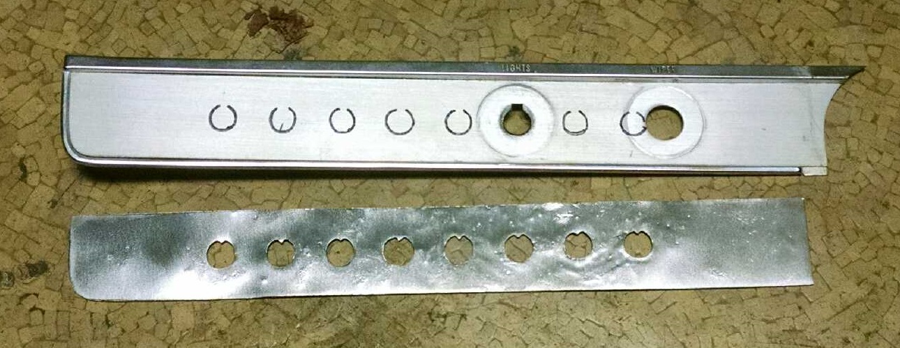
I decided to install the switches along the bottom of the dash, to the left of the steering column. There is a piece of trim there where the stock headlight and wiper switches are installed, and I figured I could modify it to take my toggle switches. The trim is shown in the photo below.
It has two holes in it, one for the headlight switch, and one for the windshield wiper switch. My goal was to adapt it to take a bunch of toggle switches that would reproduce the functions of the headlight switch, the windshield wiper switch, and the ignition switch, and some other stuff.
Here's how the trim plate looked to begin with:
Because one of the existing holes was oversized for the toggle switches, I decided to make a steel face plate that would kind of nest in the trim plate and cover up the old holes. I started by cutting a paper template to get the right shape:
The darker colored circles correspond to the size and locations of the existing holes in the trim plate. The circles that aren't colored in represent where I want to put the holes for my toggle switches. One toggle switch hole lines up with one of the existing holes, and the others are just spaced at one-inch intervals off of that hole.
Next, I put the template on a sheet of 22ga steel and just made a bunch of tick marks around its perimeter with a Sharpie:
That left an outline of the template on the sheet metal:
I cut out that piece of sheet metal...
...and verified that it fits nicely inside the shape of the trim plate:
Then I used an automatic center punch to mark the centers of the holes I'd need to drill for the switches:
Then I drilled the holes:
You might notice that the plate looks a little beat up compared to how it looked in previous photos. Because I'm terrible at drilling things, I accidentally let the drill bit grab the steel, rip it out of my hand (fortunately I was wearing heavy gloves), and wrap it around the drill bit. The photo was taken after unwrapping the steel from the bit and then hammering it flat as best I could. Footnote to that story, I recently found out that I should probably be using a unibit for metal that thin, which I now do. I always thought unibits looked like some gimmick that would be sold exclusively on TV infomercials at 2am, but apparently it's a real thing. Good to know. I've been enjoying mine since I got it.
Anyway, if you look closely, you can see that I drilled the holes undersized. I did that on purpose mostly because each toggle switch has a groove in it that is designed to be engaged by a tab, to keep the switch oriented properly. So I drilled the holes undersized, and then used a grinding bit on a Dremel to open them up until the switch would fit in, and leave a tab for the switch orientation.
An aside regarding the switch orientation feature: there is one momentary toggle, for the starter, and the rest are all just regular toggles. A momentary toggle means it only stays in the "on" position as long as you hold it there. I had used the momentary switch to check which side of the switch the locating groove was on when I made the holes. It was on the top ("on") side of the switch, the same as other toggle switches I'd used. I didn't think any more about it and put the locating tab on the top of each hole in the plate. You can probably already guess that all of the toggle switches ended up having their locating groove on the bottom ("off") side of the switch. After a lot of cursing and thinking about what to do, I looked at the switches a little closer and realized that the entire metal cover, including the threaded portion with the locating groove, could be popped off and flipped around and reinstalled. So I did that for all the other switches. It was a little tedious, but better than making a whole new face plate.
After finishing the holes in the face plate, I traced them on to the trim plate:
The trim plate was easier to drill, and less critical on hole location, since the face plate would be locating the switches.
Here's the end result, with the face plate on top of the trim plate:
Next, of course, I'd also need to put corresponding holes in the dash. I used masking tape to protect the paint and mark the hole locations:
So, here's the whole deal test fitted, after painting the face plate, with a couple of toggle switches to hold the plates in place:
After making those eight holes, I realized I'd forgotten one function, which would require another switch. Knowing that I'd forgotten one, I figured I'd probably forgotten at least one more, and there was really only room for two more switches, anyway, so I made holes to add two more switches:
When that picture was taken I was still waiting for the two additional switches to arrive in the mail, but eventually they arrived and were added:
Of course, the switches don't actually do anything until they're wired to something. I started the wiring by just adding jumpers on the back of the switches where I'd need them. This is just to group the switches that will have battery power all the time, and the switches that will only have power when the ignition is on.
That all felt like progress on the wiring and switches, and I decided to take a break from that and work on some other items.
There are still no fluids of any kind in the engine, and that was at least in part because the cooling system was not yet a closed system. Some time between the post where I put the radiator in and the start of Novengineber, I had put the upper and lower radiator hoses on, but the heater core still needed to be installed and plumbed. That was pretty straightforward, because I'd already prepared the parts. A million years ago when I was blasting parts, I'd blasted and painted the heater core enclosure. But the bottom edge of the enclosure was so badly rusted that two of the mounting bolts had broken off. To fix that, I just cut a strip of steel and drilled it with bolt holes for those two bolts, at the same spacing they would have had on the heater core enclosure. There was enough of a flange left on the enclosure so that laying that strip over the flange and putting the bolts through their bolt holes in the firewall would capture the flange between the steel strip and the firewall, clamping everything together.

Then I put on the heater hoses, and that effectively closed up the cooling system.
I was waiting on the clamp at the time I put the hoses on, but eventually I got a clamp to clamp the heater hoses to the inner wheel well and keep things a little better organized.
You can see that by the time the clamp showed up, I had the carburetor on the engine, but that's skipping ahead a bit.
It often seems like this car is as much an art project as it is a car project. A lot of choices I've made have been more for aesthetics than anything else. The carburetor I wanted for this car was only available (as far as I could tell) with a manual choke. Looking at pictures of big block Chevys with Holley carbs from the 1960s, they appear to have a choke with a thermostatic coil which, as the engine heats up, hot air is routed to the thermostatic coil, which opens the choke. Holley doesn't seem to offer that style of choke anymore, but they do offer an electric choke. The electric choke uses a thermostatic coil, as well, but it uses electric current to heat the coil. Still, the housing for the coil looks essentially the same as the housing for the coil on the old system from the '60s, so I decided to use the electric choke, for aesthetics.
So, before I put the carburetor on the engine, I converted it from the manual choke...
...to the electric choke:
The round black "pod" on the side of the carb is the housing for the thermostatic coil. Looking at it, you think it's going to be a very simple thing to convert it. Unbolt this stuff, bolt this other stuff on, done. But actually it's not real straightforward, the instructions are not real clear, and it took me a few hours to work through it all. Carburetors have a lot of tiny parts that all need to be adjusted just so for proper operation, so I don't know why I ever thought any part of it would be simple or easy.
As a bit of an aside, I had considered getting a carburetor without a choke for this car. Modern carbureted race cars typically run carbs without chokes, because the choke restricts airflow into the engine a bit, even when it is open. I drove my Monte Carlo for years without a choke, even through winters in Chicagoland. But part of the trick with that was to brake with my left foot while giving the car extra gas with my right foot until the engine had warmed up enough to run normally. That car had an automatic transmission, which made that whole operation easier. This car will have a manual trans, which would make it harder to do that. Fortunately, some research revealed that in the mid-'60s, NASCAR stock cars appeared to still have at least a choke horn on the carburetor, if not a fully functioning choke. So that made it easier to decide to get a carb with a choke on it. They also tend to be cheaper than the carbs without chokes, because those carbs tend to be among the most high-performance race carbs. So it's nice to save some money, too.
So after converting the choke over, it was pretty simple to install the carb on the engine:
Just sitting the carb on top of the manifold doesn't really count as an "installation," though, as there are still fuel lines, vacuum lines, and throttle linkage to install. So next I bent up some fuel lines, with an inline fuel filter spliced in, to bring fuel from the fuel pump to the carburetor:
That line runs up the front passenger side of the engine, from the fuel pump up to the distribution line that carries fuel to the front and rear float bowls on the carburetor. There's also a fuel pressure gauge on the distribution line, which is a luxury I've never installed on any other car I've had.


On the other side of the engine, I had to connect the throttle lingage. I really like the throttle linkage on the Impala. It seems very simple and robust. I had bought the rod that runs from the throttle lever at the firewall to the throttle connection at the carburetor, but I hadn't realized I'd need some other parts to install it. There's supposed to be a bushing at the firewall end of the rod, and I hadn't gotten that bushing. But I had a nylon spacer that I'd bought at Lowe's once upon a time, and I was able to use it to make my own bushing. The carb end of the rod is made to mate to a stock carb, I think, rather than the Holley I'd gotten, so I had to do a little adaptation there, too. The connection had some side-to-side play, so I put a small piece of a spring in there to take up the slack. It ended up being a pretty nice arrangement, which is very satisfying when you're able to piece it together with parts on hand.

For the electric choke, there is also a small hose that has to be connected from manifold vacuum to the electric choke body. Not exciting stuff, but all part of the process.
There are no hose clamps on that vacuum hose in the photo, but eventually I was able to track down some small hose clamps and put them on.
Because of the extensive customization of the dashboard, it will also require a lot of custom wiring. I had ordered reproductions of the factory wiring harnesses wherever possible, but these would all require modification to carry power and signals to and from all the new connections. The reproduction harnesses are not cheap, so that by itself was enough to create a certain level of intimidation in cutting them open. Aside from that, though, is the challenge of keeping everything straight and changing only what I wanted to change, in the manner I wanted to change it. Once you remove the outer tape from a wiring harness, it can very quickly become a giant bird's nest of wires if you're not careful to keep things organized.
So, before I cut anything open, I tried to plan out what I was going to do by drawing up a wiring diagram for what I needed to change. This may have been as much procrastination as it was planning, but it was a place to start, at least.
Since the time when I first drew that diagram, I realized that I'd forgotten a few things, and also that I was wrong about a few things, so the photo is neither complete, nor correct, but it shows the starting point. To keep the drawing simple, I only drew the things I needed to add or change. Then it's up to me to figure out how to integrate that into the rest of the wiring. The photo below shows just a couple pages out of several pages of wiring diagrams for the factory wiring.
I also took a wiring diagram and went through each harness to figure out what each connector was for and label it with a piece of masking tape, so I'd know what everything was before I started changing it.
At some point, though, it was time to start cutting stuff up. I started with the underhood wiring harness. I had thought that wouldn't need to be modified, but then I found that the installation instructions for the aftermarket ignition coil say to bypass the factory ballast resistor and run a minimum 12-gauge wire to the coil. I thought it would be cool to open up the harness and run my 12-gauge wire through the harness, so it looks stock, instead of just running another wire along the side of the harness, so I did that.
As I unwrapped the harness, every time I got to a point where the wires "branched," I put a piece of masking tape around the point where they split, so that I would remember where to put the branches when I taped it all back up.
After doing that, though ... I realized that I needed a wire routed to the electric choke, too, and also a wire for the tach signal. There were a couple other things I wasn't happy about after my first modification to the harness, so I cut it open again, added the wire for the choke, and taped it all up again. Let's hear it for efficiency.
Anyway, eventually I was ready to actually install the harness. You can see it running along the firewall in the background of the photo below:

Next, though, came the main underdash harness, which was a whole other story. This is where most of the customization and modification would be required. I basically went through it by the same method as the engine harness, but I had to add a wire for the tach, wire for the choke, then reroute some of the wires for the ignition switch so they'd run over to my toggle switches, and on and on. Also, there is an extension harness that connects the underdash harness to the harness for the taillights, and as far as I can tell nobody makes a reproduction of that harness. So, I decided to just order a couple of six-pin connectors, cut off the stock connectors, install the new connectors, and build my own extension harness, using the new connectors. All of this took a lot of time, and actually I'm not yet done with this harness. All of the major modifications are done, but I decided to get a multi-pin connector to connect the modified harness to my other modifications, and I'm still waiting for that connector to be delivered.

The other thing I did for the dashboard during Novengineber was to get a new lock cylinder for the ignition switch. I had an ignition switch left over from when I replaced the one in the truck, but I didn't have any keys for it. I figured I could just put a new lock cylinder in it, and then use it in the Impala. But, it turned out that whoever put the lock cylinder in the switch had put it in wrong, and I couldn't remove it the way it was supposed to come out. Fortunately, because it had been installed wrong, the feature that stops the cylinder from turning without a key inserted was visible through a small window in the side of the switch body. I ended up using a Dremel to grind off that feature, and then I was able to remove the cylinder and install a new one.

The last thing that needed to be connected at the carburetor was the vacuum line to the brake booster and PCV valve. These connections are often done with rubber hose, but I thought it would look better if I did it with steel hard line. I had done the same thing on the truck.
Another thing I did was to install the voltage regulator. This was another thing that I thought should be simple and straightforward, but turned out not to be. For some reason, the bolt holes in the radiator core support were larger than the bolt holes in the voltage regulator, and the voltage regulator bolts that came in the underhood bolt kit were smaller than everything. Basically, nothing fit. And, there were no threads in the holes in the core support. My Monte Carlo had one bolt for the voltage regulator where the threads had stripped out, so I had to put a nut on the back side. That made it much more of a hassle to change the voltage regulator, so I knew I didn't want to do that on the Impala.
As a solution, I ended up going to Lowe's and buying the hardware shown below:
Basically, the bolts stick through from the front side of the radiator core support. The grommets install in the bolt holes in the radiator core support, to take up the difference in size between the bolts and the holes. Then a nut goes on each bolt, to hold it in the radiator core support. This effectively creates three studs to install the voltage regulator on:
So then the voltage regulator is held onto the studs by nuts:
It does the job, and I won't need access to the front side of the radiator core support in order to replace the voltage regulator (I hope).
Another underhood detail, I installed an overflow hose for the radiator, and got a couple small clips from Lowe's to route it down the side of the radiator.
So, that pretty much sums up all the work that got done during Novengineber, aside from working on the custom O2 sensor display that I talked about in my last entry. I posted pictures of all this to Instagram, so it may look familiar, if you were following that. At some point I got tired of posting pictures of parts and wires, and I started posting a few pictures of the car. So, to wrap up this entry, here are some of those pictures.
All in all, Novengineber was great. I definitely recommend doing a themed work month if there's something you're wanting to make progress on, or get practice at. For me, posting pictures of my progress to Instagram everyday was a great way to hold myself accountable for getting something done everyday. And knowing that I was being held accountable also forced me to plan ahead and make sure that I would have parts and jobs lined up to be able to work everyday. I still haven't started the engine, but I've made a lot of progress, and I'm getting closer.