Tuesday, August 29, 2017

exhaustion

After I'd had the Monte Carlo for eight or nine years or so, the Hooker long tube headers that were on the car when I bought it rusted through and a pretty good-sized hole developed right before the collector on the passenger side.  I ordered up another pair of Hooker long tubes to replace the rusted pair, but I wasn't sure if the ones I was ordering were the same as the ones I was replacing.  I wasn't sure if the replacement headers' outlets would line up with the exhaust system that ran from the rusted headers back over the rear axle and to the mufflers, and I knew I needed to get the whole job done in one weekend, so I decided to take the situation as an excuse to get a pair of glasspacks and just run a simplified exhaust system that would exit at each side of the car just in front of the rear wheels.  That would be easy to put together, and it would mimic some of the classic race car exhaust systems from years gone by.  The glasspacks would also be louder than the relatively stock mufflers that were on the car when I got it, and louder is always cool, right?

The whole deal worked out pretty well, all in all.  The biggest problem was figuring out how to support the exhaust pipes under the car.  On a traditional exhaust arrangement where the pipes run all the way to the back of the car, it is usually easy to fit some exhaust hangers under the floor boards somewhere back under the trunk.  But trying to tuck the exhaust pipes under the floorboards with a side-exit arrangement means that it can be difficult to find enough room to fit an exhaust hanger between the exhaust pipe and the floorboard.  If you hang the pipes low enough to fit a normal-sized hanger between the floorboard and the exhaust pipe, then the pipe hangs way too low.  I tried to do what I could to get a couple hangers in place to provide some support, but it never really worked out very well.  The glasspacks and exhaust pipes ended up being essentially cantilevered off of the ends of the headers.  Despite the lack of exhaust hangers, the arrangement lasted through a few more years of service before one of the pipes broke, probably due to a combination of rust and fatigue.  Fortunately, the hangers that were on there kept the pipe from dropping off of the car completely, even though they hadn't been supporting its weight very well prior to the failure.

Anyway, I was not able to devise an adequate support system for the side-exit exhaust system at the time, and I want a side-exit exhaust on the Impala, so a better arrangement is going to have to be worked out.  I have some ideas that might work, but the guys at the body shop say they have an exhaust shop they work with, and that the guy from the exhaust shop is a genius of exhaust installation, so that has me thinking that maybe I'll have that guy work his magic on the Impala.  I'm sure the pipes he'll make will look better than what I would come up with, and I can also learn whatever his tricks are for supporting a side-exit exhaust system.  But in the mean time, I needed to come up with at least a temporary exhaust arrangement to use for the cam break-in, and until a better system can be installed.

I had another problem before I could worry about how to hang the exhaust, though.  The outlets of the headers were pointed into the transmission mount crossmember.  I wouldn't be surprised if a professional exhaust shop could probably work around this in some way, but I was trying to get some kind of exhaust hung before it went to a professional shop.  It's also possible that a solution to route the exhaust around the crossmember would create some restriction in the exhaust flow.  That's not really a big concern in my case, but I don't like seeing sharp bends in exhaust pipes, just on principle.  Anyway, I started looking at aftermarket crossmembers, to see if there were any that would give better clearance for the exhaust.

The photo below shows the exhaust outlets from the headers, and the crossmember is visible in front of them.  It has two humps in it to clear the stock exhaust arrangement, but they are too close to the centerline of the car.  The headers are set wider apart than the stock exhaust pipes would be by the time they got back to the crossmember.


The next photo shows just the passenger side exhaust outlet, and the overlap with the crossmember in the foreground is evident.


My first thought was to look for a universal crossmember, thinking that there probably wouldn't be anything ready-made to fit my application.  I thought maybe there would be something with some adjustability built into it that I could use.  I found one that looked like it might work, but when I looked around online I found more than one person saying they'd tried that crossmember, and it had so much flex in it that they could feel the shifter and transmission moving up and down when they went over bumps in the road.  That didn't sound real good to me, so I kept looking.

To my surprise, I found a Summit-brand crossmember that said it would fit 1965 Impalas, and it looked pretty beefy.  It was fabricated from square tubing and looked pretty stout.  My concern was that the humps for exhaust clearance looked like they might still be too close together, and no measurements were offered on the website.  There was a photo of the part, though, so I decided to measure the distance between the mounting bolts on my car, then measure that distance on the photo, and work out a scale multiplier to try to determine the spacing of the exhaust clearance features.  It looked like the humps were larger than they needed to be, and I thought maybe my exhaust would just clear the outside edges.  Well, I measured and calculated, and it turned out that it looked like my exhaust would actually be pretty well centered in the openings.  Looking around online, I didn't find any negative reviews of the part, so I decided to order one.

The photo below shows the aftermarket crossmember (top), as compared to the stock crossmember (bottom).


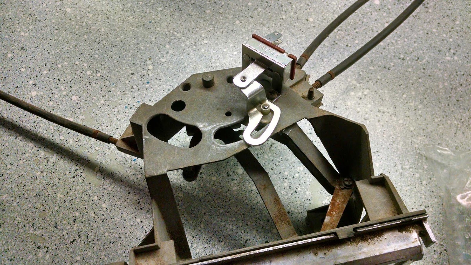
In that photo, you can see a hole in the top of the stock crossmember, toward the right hand side of it.  That is where a hook for the parking brake cable is supposed to mount.  The aftermarket crossmember doesn't have that feature, so I drilled a hole in the aftermarket crossmember in about the same spot, as shown in the photo below.


The photo below shows a close-up of those holes for the parking brake cable hook.  The section of square tubing that the hole is drilled in is totally enclosed, welded on both ends, so I drilled another, smaller hole in the bottom of it to allow any water or moisture that gets into the top hole to drain out the bottom.  The inside of the tubing wasn't painted or finished, so I tried to slop some POR-15 in through the hole on the top, to provide some corrosion protection on the inside.  Probably an ineffective waste of time, but I already had the can of POR-15 on hand, so ... why not.


Next thing was just to install the crossmember, which just bolts into place.  The photo below shows the new crossmember in place, and the exhaust outlets have a clear path to the back of the car.  In the middle of the photo you can see the jackstand that I used to support the transmission while the crossmember was out of the car.


A close-up of the passenger side exhaust outlet, showing it pointed through the hump in the crossmember:


And one more picture, which I took to show ... something ... I assume.  I don't know, it's been a while.  I really need to get caught up on this blog.


So the next thing was to work out the actual exhaust piping.  I just wanted something kind of  rudimentary in place so as not to irritate the neighbors during the cam break-in, and so as not to be too much of a nuisance on the road during test drives and when taking the car back to the body shop.  I had already picked out some mufflers, and I had a couple of short turndowns left over from when I put headers and glasspacks on the Corvair.  The plan was just to put those mufflers and turndowns in place and rig up some kind of support for them, and call that good enough as a temporary arrangement.

Glasspacks are pretty cool, but they are also pretty loud.  I decided to put glasspacks on the Monte Carlo because my buddy Allen had glasspacks on his 1967 Galaxie with a 390 in it, and I thought it sounded great.  And there were a lot of things I really liked about having glasspacks on the Monte, but there were also some drawbacks.  I used to put in earplugs if I was going to be driving more than 45 minutes to my destination.

When I decided to put glasspacks on the Corvair, I thought, "It's just a little 164 cubic inch engine, how loud could it be?"  Then one day after I'd ordered and received the parts, but before I had the car running again, I was sitting in traffic behind a Harley and it occurred to me, "That engine is not even half the size of the Corvair engine, and it is pretty loud."  It turned out that the Corvair was pretty obnoxiously loud once it was running with the glasspacks on it.  That was a lot of fun sometimes, but could also be a nuisance.

My buddy Jeff used to live in a condo maybe 50 yards from the railroad tracks, and one time when I went to pick him up, he told me when I got there, "I thought I heard your car outside about five minutes ago, but it turned out it was a train going by."  Another time, my dad had to move the Corvair out of the way in the driveway while I was in the house, and when I heard him start it up, I was amazed how loud it sounded from inside the house.  It sounded awesome, but it was a lot louder than I would have guessed it would be.  I'd never heard the Monte Carlo from inside the house, so later I asked my dad, "Is the Corvair louder than the Monte Carlo?"  He didn't even hesitate to think about it, he just said something like, "Oh, good grief, no."  So, as much as I love the sound of glasspacks, I decided that for the Impala I would look for something a little quieter, for my own comfort, and out of consideration for my neighbors.

Oh, wait, I've got one more glasspacks-are-loud story:  I once got pulled over in Burr Ridge and given a written warning for my car being too loud.  After that I generally avoided Burr Ridge for about a year, until I had some business that took me back there.  I was driving slowly through an outdoor shopping mall, just idling along and looking for the store I was trying to find.  Being that it was Burr Ridge, the street I was on was lined with parked BMWs, Audis, Porsches, and so on.  I was just driving at idle speed, probably even riding the brake, going slowly to try to read all the stores' signs.  As I was slowly making my way down that street, I thought back to that time I got pulled over and received a written warning for a loud exhaust.  I thought to myself, Man, that cop was crazy, this car is NOT that loud at all.  And right as I thought that, the noise from my exhaust set off the car alarm of a BMW that I was driving past.  OK, fine, so maybe the car was a little loud.

SO ANYWAY ... those are my stories about why I didn't order glasspacks for the Impala.  For the Impala, I wanted something that was generally shaped like a glasspack (as opposed to a boxy muffler shape), and with a good sound, but not so loud.  Another drawback to glasspacks is that over time the fiberglass packing from which they get their name will degrade and break down and blow out, and they will get louder as this happens.  I wanted to try to get something that wouldn't degrade like that, so I started looking at Flowmaster products, because I thought that all of their mufflers used chambered designs without packing that could break down.

Trying to pick out mufflers can be frustrating because you don't really know what they sound like until they're on the car.  There are videos online, but the odds of finding someone with the same engine as you, built the same way as you built it, with exhaust pipes routed the same way as yours, and all the same mufflers you're interested in comparing are not good.  And even if you did find that, a video just can't really give a good sense of what they'll sound like in person.

After looking through some information on Flowmaster's product line, I picked out the "Hushpower HP-2" muffler.  Flowmaster has a graphic that arranges their products in order of loudness, and the HP-2 falls somewhere in the middle of the range, maybe towards the louder end of the street/strip section.  It's also supposed to be the loudest of their mufflers that have an elongated shape instead of having a traditional boxy muffler shape.  I like that look better, so it was a factor for me.

I had looked at some information online and I thought that what I saw was telling me that Flowmaster's products are all chambered designs, but eventually, after I'd ordered the HP-2s, I found out that their elongated muffler designs do use a packing material which can deteriorate.  That was a little disappointing, but I already had the mufflers by the time I learned that, so I decided to just go ahead with them.  If the packing deteriorates and they get louder than I want, then I guess I'll have an excuse to try something else.

Putting all these parts together would be relatively simple, but I still needed to figure out a way to support the pipes.  I was especially worried about leaving everything cantilevered off of the headers because the engine now has aluminum heads, and I'm always worried about pulling the threads out of bolt holes in aluminum parts.  I would eventually come to realize that the exhaust manifold bolt holes in the Edelbrock heads actually come helicoiled from the factory, which is nice, but probably still better to support the exhaust somehow.

Looking around under the car, I considered a few different options for rigging up some temporary support for the exhaust.  I ended up deciding to try to use the bosses for the seatbelt mounting bolts.  The bolt holes pass through the floorpan, so if I mounted the seatbelts with long bolts that extended under the car, then I could use the extra length of the bolt as a stud to mount a bracket which could support the exhaust.

To make the brackets, I bought a length of one-inch wide, eighth-inch thick steel, took some measurements under the car, cut the steel into two smaller lengths, and bent those up into two brackets with the shape shown below.


There is an empty hole for mounting the bracket to the car, and then there is a hole at the top of the bracket, with a carriage bolt installed in that hole.  The head of the carriage bolt will butt up against the floorpan of the car, which should prevent the bracket from pivoting around its mounting point.  Probably overkill, but that's kind of how I design things, I guess.


The brackets install in the driveshaft tunnel, so I was a little worried that they would interfere with the driveshaft.  With that in mind, I tried to cut the bolts as short as I could so they wouldn't extend into the driveshaft's space any more than they had to.  It appears that everything will fit.

The photo below shows the brackets mounted under the car, looking forward towards the transmission.  You can also see the exhaust pipe lengths mounted on the reducers and running towards the back of the car.


The next photo shows the same view, but with the mufflers and turndowns installed.


And the last photo, below, shows the same arrangement, but viewed more from the side.  After the photo was taken, I bought and installed six muffler clamps to hold it all together.


So that's the exhaust setup, at least temporarily.  One step closer to being ready to fire the engine for the first time, and one step closer to being caught up on blog entries.  Because I'm playing catch-up, the first fire for the engine has actually already happened, so I'll leave you with a link to a short video with very poor quality audio of how the mufflers sound.


Sunday, August 13, 2017

fifth wheel

I've mentioned at least a few times in other entries that aesthetics are a major factor in a lot of decisions I've made on this project.  After years and years of poring through photos of old race cars and noting little details that make them what they are, I want to try to capture at least some of those little details in my project.

One feature that commonly appears on NASCAR stock cars and Trans Am sedans of the mid-'60s is the padded steering wheel.  This usually appears to be just a stock steering wheel wrapped with electrical tape.  I always used to assume that the steering wheels must just be wrapped in many, many layers of electrical tape, but it may be electrical tape wrapped over some type of padding.  Or it may be that they aren't wrapped in electrical tape at all, but rather just something that looks like electrical tape.  Either way, I've decided at this point that they are probably wrapped in something to provide some level of padding, and then that padding is covered in electrical tape to hold it all together.

I really wanted to wrap my steering wheel in electrical tape to get that look, but I figured the electrical tape would turn into a sticky mess and get pretty disgusting pretty quickly.  So I just figured I'd have to live without a wrapped/padded steering wheel.  I thought maybe I'd get a nice leather steering wheel cover to sort of give a similar effect.

But then, when I was unwrapping and re-wrapping wiring harnesses, I noticed that the electrical tape I'd bought just happened to not be anywhere near the sticky mess that other electrical tapes I'd used in the past had been.  And that got me to thinking about the steering wheel again....

The photo below shows what the stock '65 Impala steering wheel looks like.


I think it's a pretty stylish deal, with the four chrome bits positioned in pairs on each side, and the chrome horn ring that traces a chrome arc between the spokes of the wheel.  I kind of wish they'd had a horn button with the "SS" logo for the SS cars that year, but the leaping Impala logo is pretty slick, too.

For a really legit race car look, I'd have to remove the horn ring and go with a little bit more spartan appearance, as shown below.


But, I'd gotten kind of attached to the look of the horn ring, and it would be easier to make the horn work if I kept the horn ring, so I decided to exercise a little artistic liberty and keep the horn ring.

To pad the steering wheel, I ended up going to Lowe's and buying a roll of foam window seal.  The stuff I got is 3/16" thick, 3/8" wide, and comes in a roll 17' long.  And as I said above, the key to this whole deal was the electrical tape.  The stuff I used on the wiring harnesses, which wasn't a sticky mess, was 3M Highland brand vinyl electrical tape.  And the packaging even says it's fire retardant, so ... safety!


I had bought the electrical tape a while back and couldn't remember where I'd bought it from.  I tried a couple of parts stores without success and then found it at O'Reilly's.

I did a little bit of last-minute studying, looking at photos of old race car interiors, and I noticed that not everyone wrapped their wheel the same way.  For some reason I'd assumed that there would be some kind of a standard approach, but I guess it shouldn't be surprising that different people had different ideas about how to do it.  I found some photos where the whole wheel was wrapped, others where just the outer ring of the wheel was wrapped, and one photo where just the spokes and the center hub were wrapped, but the outer ring was not.  That surprised me a bit, but it also opened the door to wrap my wheel however I liked.  I decided to wrap all the exposed portions of the wheel itself, and then to install the horn ring on the wrapped wheel.

As it turned out, one 17' roll of the foam window seal wasn't enough to finish the job, so I wrapped as much as I could with one roll, taped the ends in place with electrical tape, then went and bought another roll of foam to finish the rest of the wheel.  When I was done with that, it looked like the photo below.


Next I wrapped wrapped the wheel with electrical tape, and the photo below shows it loosely in place in the car.


Next photo shows the horn ring loosely in place.


I was really pretty happy with out it turned out.  I think that if I really wanted it to be more authentic, another layer of foam and another layer of electrical tape would get the thickness about where it should be.  But I've always liked the skinny steering wheels on old cars, so I think I'll stick with just the one layer of foam.


I am a little bit worried that the first time I park the car outside in the sun, the electrical tape will still melt into a sticky mess, but the beauty of the window foam padding is that it should protect the steering wheel from the stickiness of the electrical tape, and I can just unwrap it if it ever does get messy.

So at that point, I had the wheel wrapped and loosely in place on the steering column.  But, as I mentioned a couple posts ago, I had some problems when it came time to actually torque the steering wheel in place.  The photo below shows a side view of the steering wheel as it is installed on the column.


As I said in that other entry:

I used an aftermarket steering column from a company called "ididit," which is a popular choice for aftermarket steering columns.  But it means that the factory steering wheel doesn't fit the aftermarket column perfectly, so they have a little adapter kit to make the wheel look better on their column.  It consists mainly of a little chrome ring that you essentially glue to the back of your steering wheel, and it takes up the difference in diameter between the wheel and the column.  It's a dress-up ring, in essence, as its only function is to make things look nicer.


The arrow in the photo below indicates the trim ring from the adapter kit.


The text from the other entry continues:

Well, I got the ring stuck on the back of the steering wheel, and put everything together and torqued the wheel down and ... the dress-up ring was clamped between the edge of the column and the horn ring so tightly that it was difficult to turn the steering wheel.

When I wrote that, I wondered if anyone would be able to follow my attempt at describing the problem.  Well, the arrow in the photo below indicates what I was calling "the edge of the column"...


...and the next photo below this indicates the edge of the horn ring that was clamping down on the trim ring from the other side.


Back to the text from the other entry:

So, I took everything apart, and I started trying to grind a couple of reliefs into the dress-up ring, where it contacts the steering wheel, in order to lift it away from the edge of the steering column.

The arrow in the photo below points out where the reliefs were ground in the trim ring, in order to move the trim ring away from the edge of the steering column.


I started out cutting the reliefs with a cutoff wheel on a Dremel.  That removed material pretty quickly, but it really didn't look very good.  I tried a test fit, though, as described in the other entry:

I finished that and went to put everything back together, but I realized before I even had it assembled that the back edge of the horn ring was still going to interfere with the dress-up ring, and the interference would actually be worse now, since I was essentially moving the dress-up ring forward.  So I assembled everything without the horn ring, just to check the clearance with the edge of the column.  It was improved, but still had some interference.  So, I pulled everything part again, took some more material out of the reliefs I'd made on the dress-up ring, and cut something like an eighth of an inch off of the back of the horn ring.

It was actually two or three iterations before everything fit, but at some point I decided to use a file on the reliefs in the trim ring, and that really improved their appearance.  The file made it easier to keep the relief surface flat, which gives a better appearance from the side.  I used a digital caliper to check the thickness of each relief in three places to make sure they were a uniform thickness across, and also equal in thickness to each other.

The arrow in the photo below indicates the edge of the horn ring where I cut about an eighth of an inch off to create clearance for the trim ring.


After all that, the pieces all fit together pretty well, with no interference.

One more photo below, to show what the end result looks like now.


Monday, July 31, 2017

getting heated

I talked a little bit in my first entry about how I came to be a Chevrolet guy.  And I've been so enthusiastic about Chevrolet, for so long, it seems like an inevitability, an inescapable truth.  But things could have easily turned out differently.  My dad had a 1971 Oldsmobile Cutlass when I was a kid, which I think made a strong imprint on my young psyche.  Auto manufacturers automatically become cooler when they go out of business, and sometimes I'll think that it would be cool to be an Oldsmobile guy.  I am a big fan of Cadillac's recent attempts to build a more performance-oriented image, and I think it also sort of hearkens back to the 1950s and earlier when Fords and Chevys would just get you around, and if you wanted real power under the hood you had to get a luxury brand, like Cadillac or Lincoln or Packard or Duesenberg.  Sometimes I'll think about how cool it would be to build an old high performance Cadillac project.  Also, I feel like if I hadn't picked a brand until later in life, I probably would have been a Plymouth guy.  Plymouth guys are kind of weird, and I really like the styling on a lot of the late-'60s/early-'70s Plymouths.  The 1971 Roadrunner might be my pick for the best-looking car body ever.  Plymouth also now has the bonus style points for being out of business.  AMC Javelins are cool, and so is the Rebel Machine, and I recently fell into love at first sight when I saw a 1968 AMC Ambassador SST for the first time.  Heck, on top of all that, I'll even admit that I really like the styling on Ford Galaxies and Falcons from the early '60s.  The 1971 Mercury Cyclone looks great.  There are cool old BMWs, cool old Datsuns, cool old Lamborghinis, the list goes on and on.

The point is, things could easily have turned out differently.  There are a lot of cool cars in the world, and if any one of them had grabbed my attention at the right time, maybe I wouldn't be a Chevy guy.  So, I consider myself fortunate that things turned out the way they did when I think about the advantages of being a Chevy guy.  I don't know if there's any such a thing as a cheap project car, but it would be very difficult to argue that any other make is cheaper than Chevrolet when it comes to getting parts for old models.  On top of that, it's equally difficult to argue that any other make has more parts available for old models than Chevrolet.  The aftermarket has developed so much support for the most popular Chevrolet models, it is supposedly possible to build a completely brand-new 1967-69 Camaro or 1955-57 Chevrolet, without any original frame or sheet metal to start with.  Chevelles are also very well-supported by the aftermarket.  Other Chevrolet models may not be quite as well-supported, but it is still much easier to get parts for an old Chevrolet than it is for a huge number of other old cars.  So I consider myself lucky to have become a Chevy guy at an early age.

This is all a long-winded way of arriving at the point that it is relatively easy to get reproduction parts for almost any component on an old Chevrolet.  But, when you're building a whole car from what was virtually an empty shell, eventually you're bound to find the limits of that key word, "almost."  One example of a couple parts that are not available as reproduction parts are the "bumperettes" that hang down off the front bumper.  The ones that were on my car when I got it were badly rusted, including a one-inch by three-inch hole rusted completely through one of them.  When I told the guy at the body shop that I couldn't find replacements, he recommended that I just try harder to find a used pair, because repairing the ones I had would be very expensive.  In the end, my sister somehow found a pair that someone was selling on Facebook for a fair price.

Another example ended up being the heater controls.  It's easy to find reproductions of the control head for a car with a heater and air conditioning, but I wasn't able to find any place that offered the control head for a car without air conditioning.  One of the control levers for my control head was broken, but after looking around online and not finding any easy replacements, I decided to try to fix it rather than replace it.

In the photo below, if you look carefully at the lever that is farthest down, you might be able to make out where the break is, right above the point where the control cable connects to the lever:


In the next photo below, I bent that lever at the break, to accentuate where the break is:


I think the lever may have actually been OK when I got it, and I may have broken it when I tried to test the heater controls.  In addition to moving the control cable, the lever is also connected to a switch on the top side of the control head, and I think that switch had seized up so that when I tried to force the lever through its motion, the 50-year-old pot metal lever actually broke before the switch broke loose.  I was able to find a reproduction switch to replace the seized one, but couldn't find a replacement control head.

If you can't tell what you're looking at in those close-ups, here's a shot that shows the whole control head, looking at it from the bottom:


And here's a shot that shows some of the top of it, including the switch that mounts on the top of it:


To repair the broken pot metal, I decided to try to make a small "splint" for it.  I started by cutting out a small piece of 22ga steel:


Then I drilled a hole in it and cut some reliefs on the sides, and scored it along a couple of fold lines:


The hole is there to allow the splint to fit over the pin on the top of the lever, which engages the switch.  This also serves as a locating feature to keep the splint in its proper position.

Next I slipped the splint into place, so that it fit in between the lever and the control head body, and so that it engaged that pin on top of the lever:


Next, I folded up the sides of the splint so that they ran along the sides of the lever and would keep it from bending at the break:


Then I folded the sides over the top of the lever, for more rigidity.  This is why I cut the reliefs into the sides of the splint in the first place, in order to accommodate the shape of the boss around the pin where the control cable is attached:


At that point the splint was pretty functional, but as one last step to help hold everything together and eliminate any slop in the assembly, I poured a small amount of JB Weld along the top of the lever so that it would flow down into the cracks between the lever and the splint and help to hold everything rigid.  Once the JB Weld had cured, everything seemed to work pretty well.

The last couple photos show the lever in its two most extreme positions, and the actuation of the switch as a result.  The cable attached to the lever opens a vent to allow air flow, and the switch turns on the blower fan.


At the same time that I was working on the lever, I removed the face plate and cleaned it up, polished the bezel around the faceplate, cleaned up the ends of the levers that are visible and painted them black.  The pot metal bezel is a little bit pitted with age, but it looks a lot better than it did when I got it, and good enough for my purposes.

So ... there's another thing.

Sunday, June 25, 2017

wired

If someone would have told me when I was in college that I would be 38 before I got my dream project car running and driving, I think I might have just given up on everything right then and there.  Now I am 38, I'm finally deep into this project, and if someone were to tell me that I will be 98 before I get my dream project car running and driving, I think the only thing that would surprise me would be the idea that I would live to be 98.

You just can't appreciate what it takes to build a car until you do it.  Or at least, I didn't.  And I really thought I did.  I really thought I had a pretty good handle on it.  But it's just every little thing.  Every little thing, over and over.  You can plan on major things, like the engine rebuild, selecting a transmission, what to do with the rear end.  Body work.  Interior.  What I didn't appreciate when I decided to start this project with essentially an empty rolling shell, was just how much every other little thing adds up to.  When you start with an empty shell, you need everything.  And that was part of the appeal for me, knowing that when I was done, everything would be new.  But it also means you need everything.  A voltage regulator.  Horns.  Door locks.  Speedometer cable.  A windshield wiper motor.  Windshield wipers.  The emblem that goes on the glove box door.  The little screws that are used to adjust the direction of the headlights.  The little screws that are used for every other little thing.  The push nuts that hold the Bowden cable ends on the lever arms for the heater vent adjustments.  And on and on.

But it's not just that you have to procure all those things.  You also have to install them.  And nothing ever seems to go together as easily as it should.  As an example of how small things can turn into massive time sinks, a while back I spent probably at least three hours, maybe five, spread across three days, trying to install the steering wheel.  That's the time I was actually working on it, it's not counting the time I spent waiting for adhesive to cure.  I used an aftermarket steering column from a company called "ididit," which is a popular choice for aftermarket steering columns.  But it means that the factory steering wheel doesn't fit the aftermarket column perfectly, so they have a little adapter kit to make the wheel look better on their column.  It consists mainly of a little chrome ring that you essentially glue to the back of your steering wheel, and it takes up the difference in diameter between the wheel and the column.  It's a dress-up ring, in essence, as its only function is to make things look nicer.  And you just glue it on with some silicone.  Easy, right?

Well, I got the ring stuck on the back of the steering wheel, and put everything together and torqued the wheel down and ... the dress-up ring was clamped between the edge of the column and the horn ring so tightly that it was difficult to turn the steering wheel.  So, I took everything apart, and I started trying to grind a couple of reliefs into the dress-up ring, where it contacts the steering wheel, in order to lift it away from the edge of the steering column.  I finished that and went to put everything back together, but I realized before I even had it assembled that the back edge of the horn ring was still going to interfere with the dress-up ring, and the interference would actually be worse now, since I was essentially moving the dress-up ring forward.  So I assembled everything without the horn ring, just to check the clearance with the edge of the column.  It was improved, but still had some interference.  So, I pulled everything part again, took some more material out of the reliefs I'd made on the dress-up ring, and cut something like an eighth of an inch off of the back of the horn ring.  That put me at the end of the weekend, with the steering wheel sitting in the garage with a weight holding the dress-up ring in place while the silicone adhesive dried.  Monday night after work I installed the wheel again, and everything finally fit together well.  But this was all just to get the steering wheel installed, which had seemed like it should have been maybe a twenty minute job, at most.

Anyway, in spite of the complete lack of progress on this blog, progress on the car has been slowly creeping forward.  In fact, a lot of work has gotten done that hasn't been written up yet.  I kept thinking that I needed to get the blog caught up, but the idea of writing an entry that would cover everything that's been done was so daunting, I kept putting it off.  Obviously, that only makes the problem worse.  In general I've been trying to write things up in the order they happen, but I think I'm going to take a different tack.  I think I'm going to break things down into subsystems, and write those up in separate entries, to make the work easier to manage in chunks.

In my last entry, I talked about some of the work on the dash wiring and the custom switch panel.  I'll focus the rest of this entry on how that electrical work got finished.

I was planning to use several relays in order to reproduce the functions of the stock ignition switch and the stock headlight switch.  For example, when the ignition switch is turned to the cranking position, it also cuts power to the accessories, to send as much power as possible to the starter motor and ignition system.  To do this with toggle switches, relays can be used to interrupt certain circuits when other circuits are closed.  Anyway, I needed a place to mount some relays.

I started by finding a place under the dash where it looked like there would be enough room to fit the relays, and also a convenient place to mount them.  There is a sort of a "shelf" at the bottom of the dashboard, right behind where my switches were being mounted, and there was a bolt hole already there that I could use to mount a bracket for my relays.

Next, I roughed out the approximate shape of a mounting bracket in cardboard, then flattened that cardboard and transferred the shape to a piece of sheet metal:


Cut that out:


Folded it up into the shape I needed:


And drilled some holes for mounting:


The four holes on the upper surface are for mounting the relays, the big hole on the lower surface is for mounting the bracket itself.  The smaller hole on the lower surface is just there to clear the end of another screw that the bracket overlaps.

With the relays mounted:


A recurring theme of the project, I realized I'd forgotten a function that would require another relay.  So I had places for four relays, but I needed to mount five.  But, I was able to mount the fifth relay off the side, using the same mounting hole as the relay on that end of the row:


I used a label maker to tag each relay with an abbreviation of its function.  You'll sometimes see old race cars with labels like this on their dashboards, so I'd bought the label maker to be able to label the functions of all my toggle switches.  It would have been easy to spend a lot more time and/or money on nicer-looking labels, but the bottom line on race cars is functionality.  Since my project is sort of a race-car-tribute, this emphasis on functionality can often be a convenient justification for a cheap and effective solution.

In my last entry, I showed that I had started wiring some of the switches together in groups.  But when I started to try to run more wires to the switches, I quickly realized that wiring them in place was not going to work.  It was nearly impossible to see what I was doing with them installed in the dash, and the wires were all ending up too long and it was turning into a mess.  I took a break to try to come up with a better plan, and decided to build up a switch-and-relay module off of the car, then install it as an assembly.

I took some rough measurements of where the relay bracket was relative to the switches, and then I pulled everything out of the dash.  I installed the switches loosely in their faceplate, to keep them organized relative to each other, and then I started running wires at the appropriate lengths to position the relays where they needed to be.


I labeled the plugs that connect to the relays, so that if everything ever has to come apart, it will be easy to match things back up when it's reassembled.

In the picture above, I have the switches wired to each other, and I have the relay wiring grouped by function.  The relays each came with a plug with wires running to it (a "pigtail" in the parlance of the automotive parts industry).  So I grouped them by which ones would be connected to ground, which ones would be connected to battery positive, etc.

In the picture below, I added more wires for integrating the switch-and-relay module into the car's wiring harnesses.  These were labeled with temporary masking tape labels so I could remember what their function was until I had them connected at the other end.


The last thing was to take all those wires that would be connected to the underdash wiring harness and run them into a large, multi-pin connector.


This would allow me to just install the whole assembly under the dash and then plug it in, instead of having to do a lot of electrical splicing under the dash.  Also, it can be disconnected if anything ever has to be removed for maintenance or repair, instead of cutting a bunch of splices out.


The photo below shows the whole deal installed under the dash.  


At this point, the gauges aren't installed, so you can see the relays mounted just behind the toggle switches, which are just to the left of the steering column.

A little bit closer look:


A I mentioned in my previous entry, I had also cut open the main underdash wiring harness and modified it to run various wires where I needed them to go.  The stock ignition switch is to the right of the steering column, for example, and I was moving almost all of its functions over to the toggle switches on the left side of the column, so those wires needed to be rerouted.

After those modifications were finished, I put the harness in the car and put the other side of the large multi-pin connector for the relays and switches on that harness so that it could be connected.  Once that was hooked up, that pretty much wrapped up the functionality of the switch panel, which was a pretty major accomplishment for the customization of the dashboard, and also for the functionality of the car.

But there was still a lot of other work to be done on the dashboard.  In reality, a lot of this work was going on in parallel, but it's easier to present it in series.  Anyway, here I've described the work on the relays and toggle switches; in the last entry, I talked about mounting the toggle switches in the dash and starting to modify the wiring harnesses; in the entry before last, I talked about the work I did on the O2 sensor display; in the entry before that one, I talked about the work I did to be able to mount some aftermarket gauges in the dash.  All this still leaves two other major items for the completion of the dash:  a warning light display for the left-hand pod in the dashboard, and the wiring of all the custom gauges.

The process for making the warning light display was kind of similar to the process for making the O2 sensor display, in that there was a stock housing for a gauge cluster that went in that pod, and I was adapting that housing to hold my warning light display.  But it would end up being a lot less complicated than the O2 sensor display.

The left-hand pod in the stock dashboard housed four small gauges, which displayed water temperature, oil pressure, an ammeter, and a fuel gauge.  All of those functions were going to be monitored by my aftermarket gauges, so I wanted to do something else with the pod there.  I decided to make a small cluster of warning lights to put in there.

My original idea was to make a faceplate that would sort of emulate the shape and arrangement of the gauges that went in the stock cluster, and then to make some lenses for the warning lights that would go behind that faceplate.  My first crack at a faceplate came out looking like something that someone had hacked out of a piece of sheetmetal with a Dremel, probably because that's what I'd done.  I tried to be careful to make it look nice, but ... it didn't.

The more I thought about it, the more complex I realized it was going to be to make what I was envisioning.  When I went through the debacle of trying to cast a lens for my O2 sensor display, I came to appreciate what a hassle that was going to be.  I gave up on trying to cast custom lenses, which ended up simplifying the warning light cluster, too.

As I said earlier in this entry, race car aesthetics are usually born of simplicity and functionality, which can be a really convenient justification for simple and functional solutions on my project, as well.  In the case of the warning light cluster, I ended up just buying four round warning lights which could be mounted in a simpler faceplate design.


Mounting the lights inside the pod of the stock dash would be a little bit nicer than what a real race car would probably have, but the simplicity of popping a few off-the-shelf warning lights into a plate would also mimic the race car aesthetic.

Testing with a 9V battery:


Next, to identify what each earning light represented, I ordered a sheet of dry transfer letters and numbers off of Amazon.  They're intended for model railroaders, but it's just a sheet of black letters in various sizes.  I abbreviated the functions of the lights, to fit larger letters on the small lights:


OIL -- oil pressure (lights when too low)
TEMP -- coolant temperature (lights when cold and when too hot)
GEN -- generator system fault (lights when alternator is not charging)
BRK -- brake system fault (lights when brake system is losing pressure, or when parking brake is set)

When a light is lit, the lettering is clearly visible, but when the lights are not lit the lettering is much less noticeable:


So the last major thing to do for the dashboard was to install the O2 sensor pod, the warning light pod, all the aftermarket gauges, and then to wire them up.  The main things that needed wiring were switched power to each gauge, a ground for each gauge, and then the backlights for the gauges.

The plastic frame that holds everything has a few metal studs threaded into it which are used for connecting grounds in the stock arrangement.  Because they're electrically isolated from each other by the plastic frame, I decided to use them as junction posts to connect the gauges.  I used two posts as grounds, one post as a switched positive junction, and one as a junction for the power to the backlights.  That made it easy to tie everything in the gauge cluster to those junction posts, and then there are only four connections to make when the cluster is installed in the dash.


The front side:


The green lights on either side of the tachometer are the turn signal indicators.  The amber light is to indicate when the high beams are on.

Here it is in the car:


And here's a little bit more wide-angle view: 


You can see in these last two photos that I had added labels for the toggle switch functions.  You can also see that I covered the trim piece under the glovebox with stickers for some of the aftermarket companies I've bought parts from.  The trim piece was a little scratched and dented, and I had all these stickers that had come with the products, so it seemed like a good way to dress up the dented trim piece for free.  I like it.

So that pretty much wraps up the modification and customization of the dashboard display.  This represented a major step towards being able to run the engine and make the car functional.  At the same time that this was progressing, I was also working on several other subsystems of the car.  Updates on those still to come.